Display with an electro-optical display module

a display module and display technology, applied in non-linear optics, instruments, optics, etc., can solve problems such as unsatisfactory gaps or joints, and achieve the effect of avoiding undesired gaps or joints

Active Publication Date: 2016-05-10
CONTINENTAL AUTOMOTIVE GMBH
View PDF10 Cites 0 Cited by
  • Summary
  • Abstract
  • Description
  • Claims
  • Application Information

AI Technical Summary

Benefits of technology

[0006]An object of the invention is to specify the above displays with trim elements or information elements so that no undesired gaps or joints occur. This object is achieved by virtue of the fact that the surface of the transparent cover is configured in a three-dimensional fashion. Consequently, it is possible, owing to the three-dimensional configuration, to implement trim elements such as scale rings, for example, without the occurrence of undesired gaps or joints. When the cover is bonded onto the display area only in sub-areas, it is possible to provide additional components between the transparent cover and the display area. If the transparent cover is bonded in the sub-areas of the display area, which can be perceived by a possible observer, the result, firstly, is that the display area that can be perceived by the observer has a uniform appearance, and secondly it is possible to mount in the regions of the cover configured in a three-dimensional fashion, for example as a trim or scale ring, additional components under the trim rings or scale rings, for example, in order to be able to illuminate them separately.
[0007]The cover can be produced in a particularly simple and inexpensive fashion when it consists of a film. The three-dimensional design of the film can be implemented particularly easily by deep-drawing the film. The three-dimensional configurations of the film are particularly effective when they are printed. When a film is being printed it is useful to print the film before the deep-drawing since it is then substantially easier to print. When the film is printed on the side averted from the possible observer, the printing is protected against mechanical abrasion, for example when the display is used as an input device.

Problems solved by technology

When trim elements or information elements, such as scale rings for example, are mounted on the cover, undesired gaps or joints occur.

Method used


Image

  • Display with an electro-optical display module
  • Display with an electro-optical display module
  • Display with an electro-optical display module

Examples


Embodiment Construction

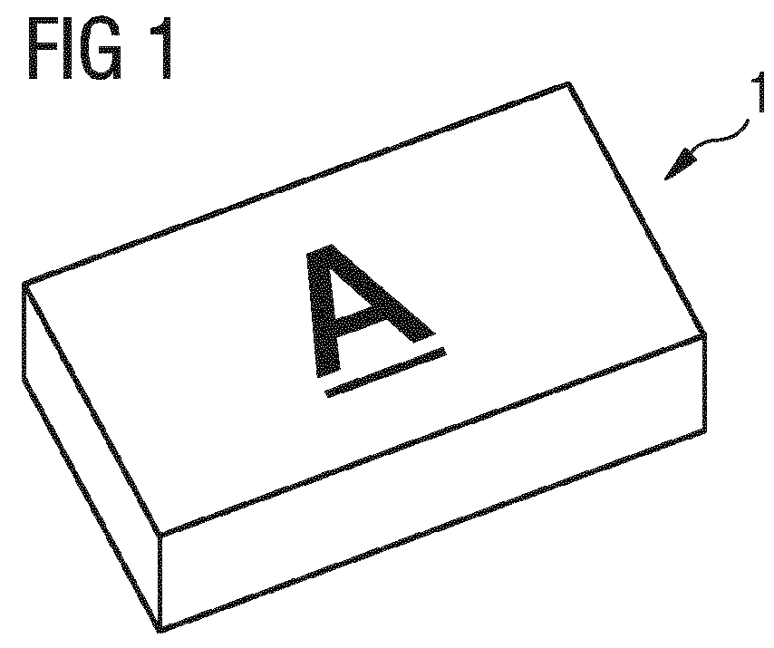
[0015]The electro-optical display module in FIG. 1 is configured, for example, as a liquid-crystal display and has a display area A which usually covers virtually a complete side of the display module. The display module can, for example, be configured as a point-matrix display; there are, however, also other possible electro-optical display modules.

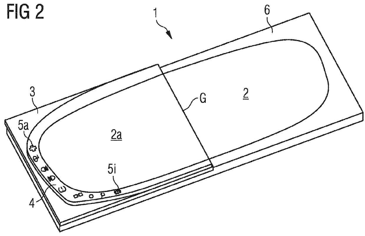
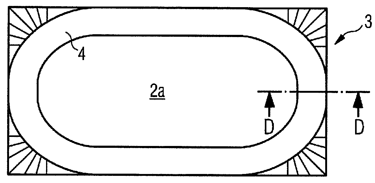
[0016]The first exemplary embodiment of the inventive display in FIG. 2 shows the electro-optical display module 1 having the display area A and shows a cover 3 of which only half is illustrated and which has a three-dimensional structure 4. Backlit symbols 5a to 5i are illustrated in the three-dimensional structure 4 configured as a trim frame. The symbols 5a to 5i can, for example, be implemented by printing the cover 3. The print can be configured thereby such that the symbols can be perceived only when they are appropriately backlit. This is possible, for example, by applying to the printed symbols in the direction of a possible obse...


PUM

PropertyMeasurementUnit
diameteraaaaaaaaaa
transparentaaaaaaaaaa
refractive indexaaaaaaaaaa

Abstract

A display with an electro-optical display module has a display area, with a light-transmissive cover arranged between the display area and a possible observer of the display area. The light-transmissive cover is bonded onto the display area by an adhesive, and provision is made for the surface of the light-transmission cover to be configured in a three-dimensional fashion.

Description

CROSS REFERENCE TO RELATED APPLICATIONS[0001]This is a U.S. national stage of application No. PCT / EP2012 / 076056, filed on Dec. 19, 2012. Priority is claimed on German Application No. DE102011089266.4, filed Dec. 20, 2011, the content of which is incorporated herein by reference.BACKGROUND OF THE INVENTION[0002]1. Field of the Invention[0003]The invention relates to a display with an electro-optical display module, having a display area and a transparent cover arranged between the display area and a possible observer of the display area, the transparent cover being bonded onto the display area by a transparent adhesive.[0004]2. Description of Prior Art[0005]Electro-optical display modules are, for example, liquid-crystal displays or organic light-emitting diodes displays used, for example, as displays or combined display and input areas, for example in cell phones. In order to protect electro-optical display modules, they are additionally covered with transparent covers bonded onto t...

Claims


Application Information

Patent Timeline
Patent Type & Authority Patents(United States)
IPC IPC(8): G02F1/1335G02F1/1333G02F1/1339
CPCG02F1/133524G02F1/1333G02F1/13392G02F1/133308G02F2001/133311G02F2001/133331G02F2202/28G02F1/133311G02F1/133331
Inventor MARQUARDT, HELMUTPAWUSCH, WOLFGANG-PETERWEDEL, HANS
Owner CONTINENTAL AUTOMOTIVE GMBH
Why Eureka
Try Eureka