Air vent for a vehicle

a technology for air vents and vehicles, applied in vehicle components, vehicle heating/cooling devices, transportation and packaging, etc., can solve the problems of rapid decrease in operating force and decrease in overlap amount, so as to improve the operating feeling of the vane, reduce shock noise and operational noise, and prevent a deviation of operating force

Active Publication Date: 2016-06-07
NIFCO KOREA
View PDF42 Cites 6 Cited by
  • Summary
  • Abstract
  • Description
  • Claims
  • Application Information

AI Technical Summary

Benefits of technology

[0014]The vehicle air vent according to the present invention can improve the vane operating feeling via the damper bushing connected to the vane hinge shaft, reduce shock noises and operational noises to external loads, and prevent a deviation of the operating force, which is caused by temperature change. Moreover, the uniform operational force can be ensured, and even during long-time use, the vane operating force does not change.
[0015]Since the operating force can be adjusted by adjusting the hardness of the damper bushing, even when a mold is not modified, the vane operating force can be managed, the frictional durability of the hinge connection site is improved, and the operational reliability can be ensured.

Problems solved by technology

However, when the horizontal operating force of the vane 220 is adjusted by adjusting the overlap amount as in the conventional vehicle air vent, a deviation of the operating force becomes sharp with a change of the overlap amount in dimension of each objects, and the overlap amount decreases due to wear caused by friction between plastics, resulting in a rapid decrease in the operating force.

Method used


Image

  • Air vent for a vehicle
  • Air vent for a vehicle
  • Air vent for a vehicle

Examples


Embodiment Construction

[0021]Specific technical concepts of the present invention will be described below in detail based on an embodiment shown in appended drawings.

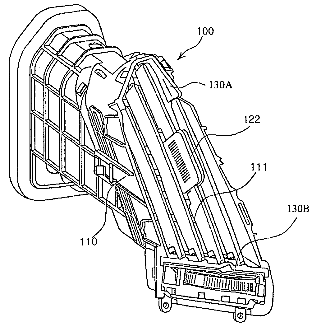
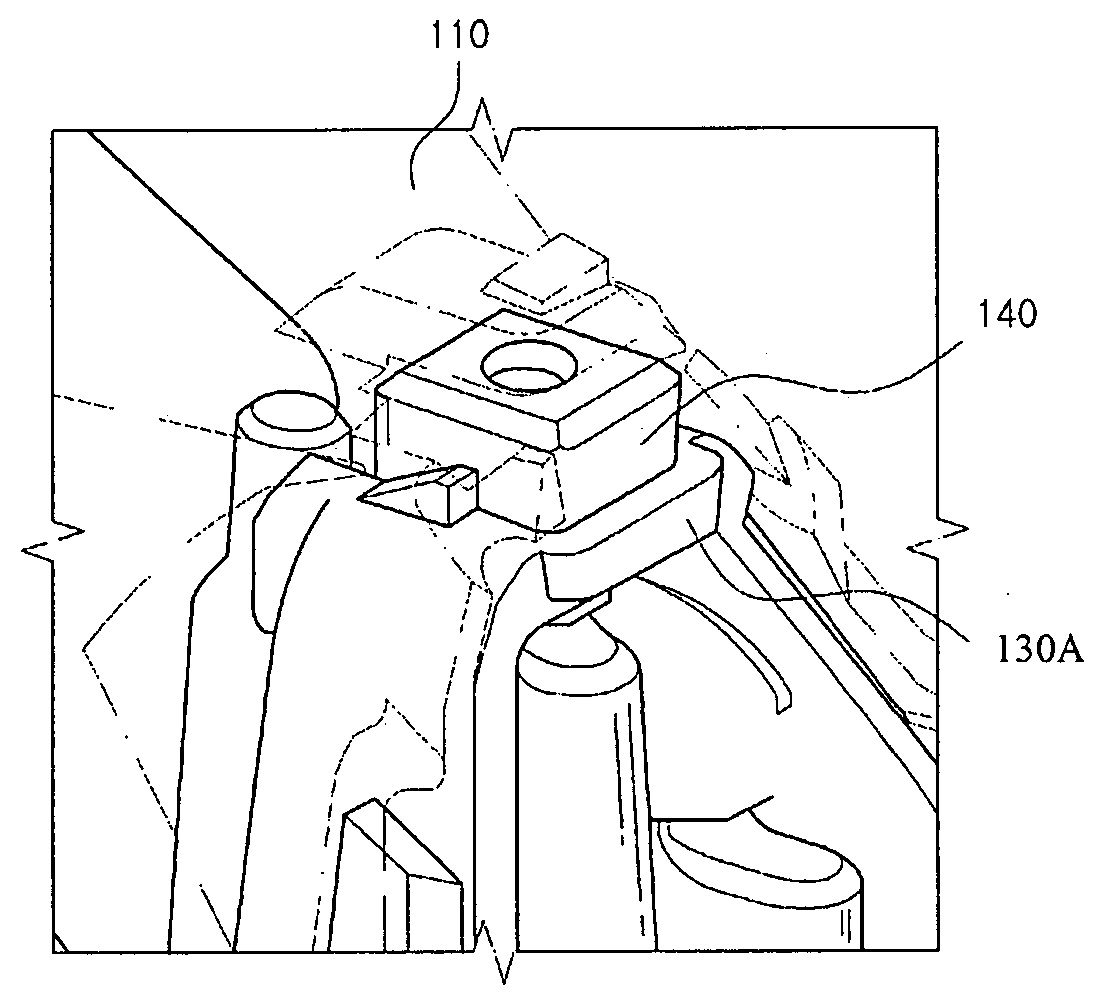
[0022]FIG. 2 is a perspective view of one embodiment of the present invention, FIG. 3 is an enlarged perspective view of an upper hinge shaft site of a vane in accordance with one embodiment of the present invention, and FIG. 4 is an enlarged perspective view of a lower hinge shaft site of the vane in accordance with one embodiment of the present invention.

[0023]FIG. 5 is a sectional view taken along a line A-A in FIG. 4.

[0024]As shown in FIG. 2 to FIG. 5, in a vehicle air vent 100 according to the present invention, a plurality of vanes 120 is provided in an air discharge port 111 of a body 110 so as to be rotatable in a horizontal direction. By coupling the vanes 120 to each other, when a knob 122 provided on one vane 120 is operated, all of the vanes 120 are rotated together, and a hinge shaft 121 provided at each of an upper end and a low...


PUM


Abstract

A vehicle air vent includes a plurality of vanes installed in an air discharge port in a body to be rotatable in a horizontal direction. By coupling the vanes to each other, when a knob provided on one vane is operated, all of the vanes are rotated together, and a hinge shaft provided at each of an upper end and a lower end of each vane is inserted into and connected to a hinge hole of a spacer provided at each of an upper end and a lower end of the air discharge port of the air vent body. A damper bushing connected to a front end portion of the vane hinge shaft passing through the hinge hole is installed below the hinge hole of a spacer to which each hinge shaft of the vane provided with the knob is connected.

Description

FIELD OF THE INVENTION[0001]The present invention relates to a vehicle air vent that guides external air to the inside of a vehicle, and in particular, a vehicle air vent capable of stably keeping a horizontal operating force of vanes installed in an air discharge port of an air vent body.BACKGROUND ART[0002]Generally, in the vehicle air vent, a plurality of vanes is rotatably provided in the air discharge port of the body to adjust the direction of air discharged to the inside of the vehicle and seal the air discharge port of the body.[0003]In the vehicle air vent, since a plurality of vanes is coupled to each other, when a knob provided on one vane is operated, all of the vanes are rotated together.[0004]A hinge shaft to be inserted into and connected to a hinge hole of the air vent body or a spacer is provided at each of an upper end and a lower end of each vane.[0005]FIG. 1 is a perspective view of a vane hinge shaft connecting site of a conventional vehicle air vent.[0006]As sh...

Claims


Application Information

Patent Timeline
Patent Type & Authority Patents(United States)
IPC IPC(8): B60H1/34
CPCB60H1/3421B60H2001/3464B60H1/30B60H1/34
Inventor PARK, KI YOUNG
Owner NIFCO KOREA
Why Eureka
Try Eureka