Index matched grating inscription

a technology of index matching and inscription, applied in the field of optical fibers, can solve problems such as unsatisfactory intensity variations within optical fibers

Active Publication Date: 2016-08-30
OFS FITEL LLC
View PDF8 Cites 0 Cited by
  • Summary
  • Abstract
  • Description
  • Claims
  • Application Information

AI Technical Summary

Problems solved by technology

This phenomenon, known as lensing, results in undesirable intensity variations within the optical fiber.

Method used


Image

  • Index matched grating inscription
  • Index matched grating inscription
  • Index matched grating inscription

Examples


Embodiment Construction

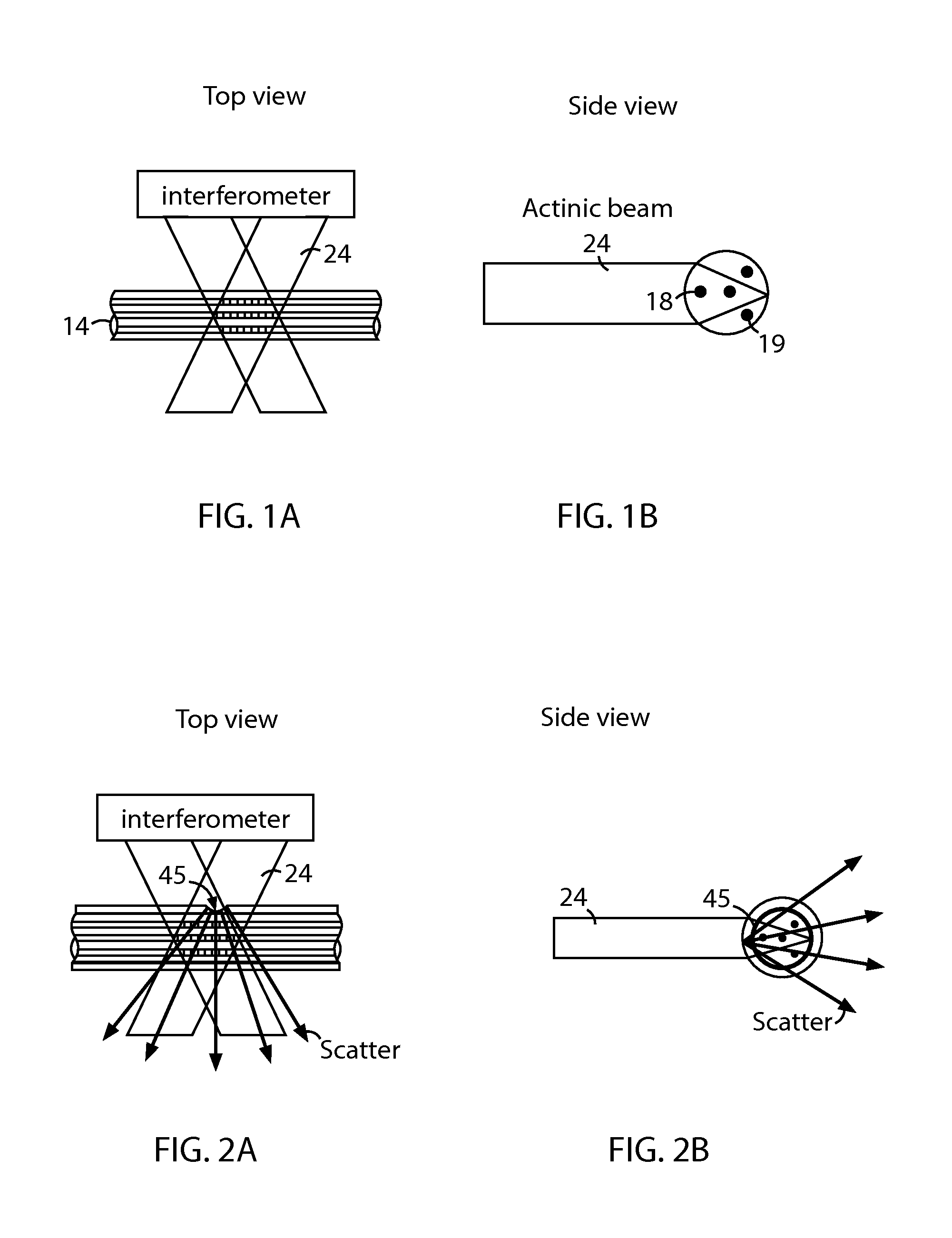
[0025]Gratings are often inscribed onto an optical fiber by exposing photosensitive regions of the optical fiber, such as the core, to an interference pattern of actinic radiation (e.g., ultraviolet (UV) light). As shown in FIG. 1B, the optical fiber is often cylindrical in shape. Thus, when an actinic beam irradiates the optical fiber from a direction that is transverse to the cylindrical axis, such as that shown in FIGS. 1A and 1B, the curvature of the optical fiber causes focusing of the UV light, as shown in FIG. 1B. This phenomenon, known as lensing, results in undesirable intensity variations within the optical fiber. For example, as shown in FIG. 1B, when an actinic beam 24 irradiates a multi-core fiber 14, depending on the configuration of the cores within the multi-core fiber 14, the actinic beam 24 may irradiate some cores 18 but wholly avoid other cores 19 due to the lensing effect. As one can appreciate, lensing can be even more complicated in fibers that do not have a c...


PUM


Abstract

The disclosed embodiments provide systems and methods for mitigating lensing and scattering as an optical fiber is being inscribed with a grating. The disclosed systems and methods mitigate the lensing phenomenon by surrounding an optical fiber with a liquid index-matching material that is held in a vessel. The disclosed systems also include a replenishment mechanism that replenishes the liquid index-matching material as the optical fiber is pulled through the vessel.

Description

CROSS REFERENCE TO RELATED APPLICATIONS[0001]This application claims the benefit of U.S. provisional patent application Ser. No. 61 / 767,270, filed on 2013 Feb. 21, having the title “Index Matched Grating Inscription,” which is incorporated by reference in its entirety as if expressly set forth herein.BACKGROUND[0002]1. Field of the Disclosure[0003]The present disclosure relates generally to optical fibers and, more particularly, to optical fiber gratings inscription.[0004]2. Description of Related Art[0005]In optical fibers, gratings are often inscribed by exposing photosensitive regions of an optical fiber, such as the core, to actinic radiation, such as ultraviolet (UV) light. Specifically, an interference pattern is generated from the actinic radiation by, for example, using an interferogram or other known technique.[0006]Due to the cylindrical shape of the optical fiber, when UV light irradiates the optical fiber from a direction that is transverse to the cylindrical axis, the c...

Claims


Application Information

Patent Timeline
Patent Type & Authority Patents(United States)
IPC IPC(8): G02B6/02
CPCG02B6/02104G02B6/02152G02B6/02128
Inventor FEDER, KENNETH SWESTBROOK, PAUL S
Owner OFS FITEL LLC
Why Eureka
Try Eureka