

Method of manufacturing laminated core
a manufacturing method and technology of laminated cores, applied in the direction of electrical equipment, dynamo-electric machines, chemical instruments and processes, etc., can solve the problems of poor workability, achieve the effect of convenient breakage, optimize flow rate, flow rate and resin amoun
- Summary
- Abstract
- Description
- Claims
- Application Information
AI Technical Summary
Benefits of technology
Problems solved by technology
Method used
Image

Examples
first embodiment
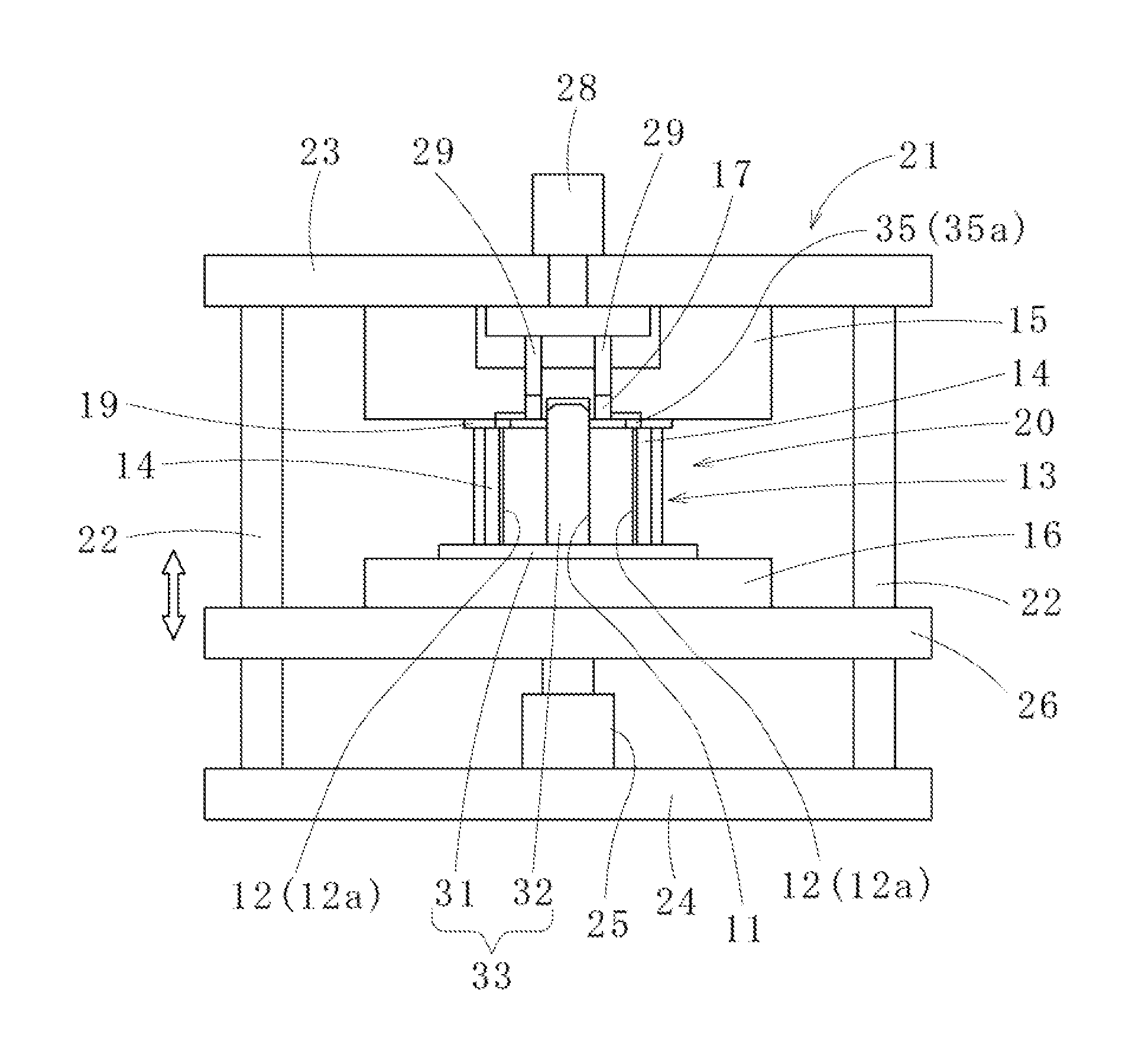
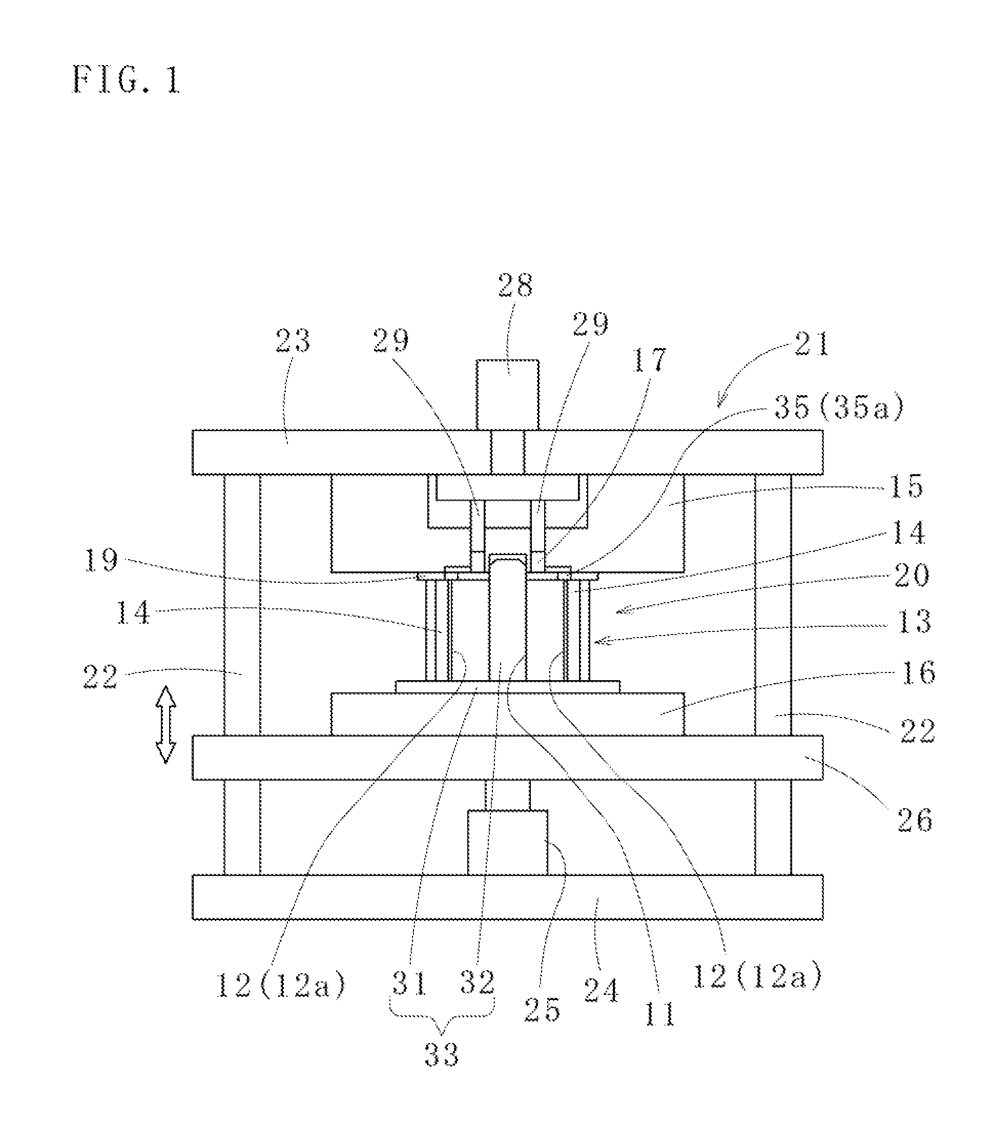
[0033]Referring to the accompanying drawings, embodiments of the present invention will be described for a better understanding of the present invention. As shown in FIGS. 1 and 2, the present invention provides. a method of manufacturing a laminated core (e.g., a laminated rotor core used for a motor rotor) 20 including laminating a plurality of core sheets 10 to form a core body 13 having a central through-hole 11 and plural pairs of magnet insertion holes 12, 12a located around the through-hole 11, inserting permanent magnets. 14 in each of the magnet insertion holes 12, 12a, and while holding the core body 13 between an upper die 15 and a lower die 16 (both are examples of die devices), injecting a resin (usually, a thermosetting resin such as an epoxy resin) 18 into the magnet insertion holes 12, 12a via a dummy plate 19 from resin reservoir pots 17 each having a circular cross-section and each provided in the upper the 15 (or the lower die 16) to fix the permanent magnets 14. ...
third embodiment
[0044]Referring to FIG. 8, a method of manufacturing a laminated core according to the present invention will be explained. In this embodiment, resin reservoir pots 44 are provided in an upper die 42 such that each of the resin reservoir pots 44 is arranged in a different position from the gate holes 35, 35a provided in a dummy plate 43 in a plan view. The dummy plate 43 includes runners 45, 45a guiding the resin 18 from the resin reservoir pots 44 to the gate holes 35, 35a, respectively. Each of the runners 45, 45a has a groove shape (e.g., a rectangular groove shape) in cross-section. Also, an end of the runner 45 (or 45a) does not have to completely overlap with the resin reservoir pot 44. It is sufficient that a region of the runner 45 (or 45a) equal to or larger than a cross-sectional area of the runner 45 (or 45a) is exposed to the resin reservoir pot 44.
[0045]In the method according to the third embodiment, by removing the dummy plate 43 from the core body 13, each inlet face...
PUM
| Property | Measurement | Unit |
|---|---|---|
| stress concentration | aaaaa | aaaaa |
| stress concentration | aaaaa | aaaaa |
| workability | aaaaa | aaaaa |
Abstract
Description
Claims
Application Information