
Frictional part with a zig-zag or undulating circumferential groove in the frictional surface
A technology of friction components and friction surfaces, applied in the direction of friction linings, friction clutches, clutches, etc., can solve the problems of limited controllability of friction action devices and undesired torque transmission, and achieve the effect of improving wear characteristics
Patent Information
- Authority / Receiving Office
- CN · China
- Patent Type
- Patents(China)
- Current Assignee / Owner
- Publication Date
- 2012-11-14
Smart Images
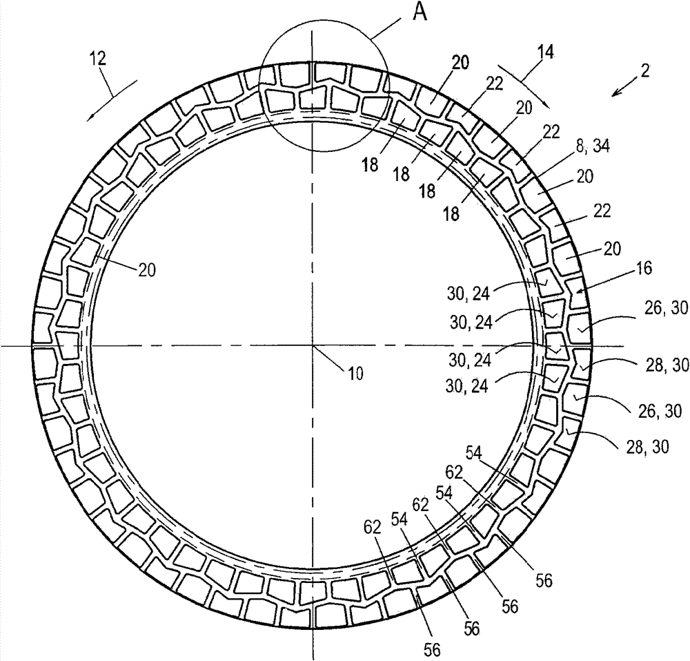
Figure 1 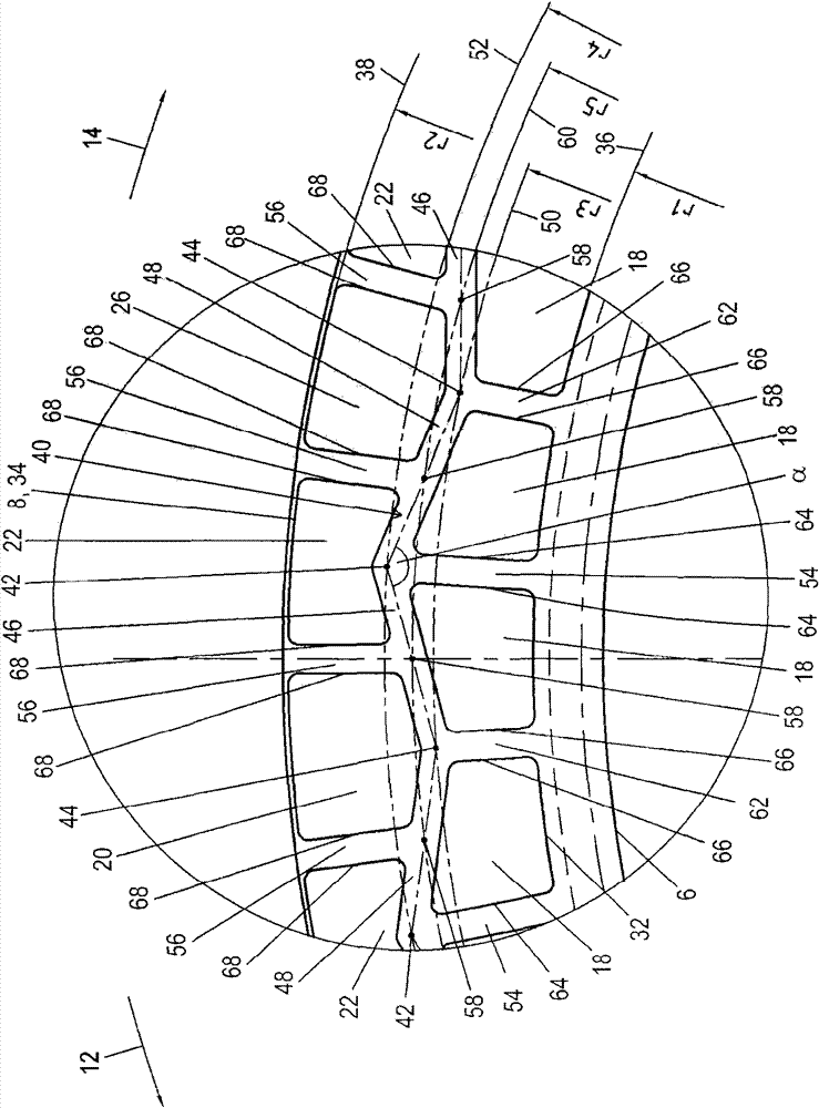
Figure 2 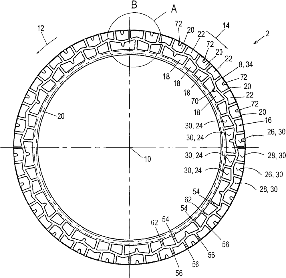
Figure 3
Abstract
Description
technical field
[0001] The invention relates to a friction element, such as a friction plate for a friction action device such as a multi-plate clutch, which has an annular friction surface with an inner edge and an outer edge. A first circumferential groove is provided in the friction surface, the first circumferential groove extending between the radially inner and radially outer deflection points in a zigzag or undulating manner. Background technique
[0002] The prior art discloses friction components for friction action devices, in particular plates for multi-plate clutches, which essentially consist of an annular friction lining carrier and a friction lining, which is attached On at least one side of the friction lining carrier, an annular friction surface is formed. The friction lining generally comprises a fibrous material produced from a paper-containing material or otherwise produced from carbon. In contrast, the friction lining carrier is generally formed from a...
Examples
Embodiment Construction
[0048] figure 1 with figure 2 A first embodiment of a friction component 2 for a friction device according to the invention is shown. The shown friction component 2 is designed in this variant as a plate for a multi-plate clutch or multi-plate brake and has a friction lining carrier 4 . The friction lining carrier 4 is embodied as an annular steel disk which extends in the plane of the drawing and has an inner edge 6 and an outer edge 8 . A drive profile, preferably an internal toothing, is provided on the inner edge 6, which is only schematically represented in the figures and which is integral with the annular disc. The internal toothing serves to rotationally fixedly connect the friction part 2 to a disk carrier, but enables an axial movement of the friction part 2 along the disk carrier. The present friction part 2 is thus a so-called inner disc. However, it should be noted that the friction part 2 according to the invention could also be an outer disc, wherein then a...