
Rudder propeller
a technology of rudder propeller and propeller shaft, which is applied in the direction of propeller components, toothed gearings, propulsive elements, etc., can solve the problems of considerable load on the planetary gearing during the operation of the rudder propeller, and the coupling of this kind known from the prior art is not only complex, but also wear-related, so as to improve the wear behavior, improve the load compensation, and improve the effect of cos
Patent Information
- Authority / Receiving Office
- US · United States
- Patent Type
- Applications(United States)
- Current Assignee / Owner
- Publication Date
- 2013-11-07
- Estimated Expiration
- Not applicable · inactive patent
Smart Images
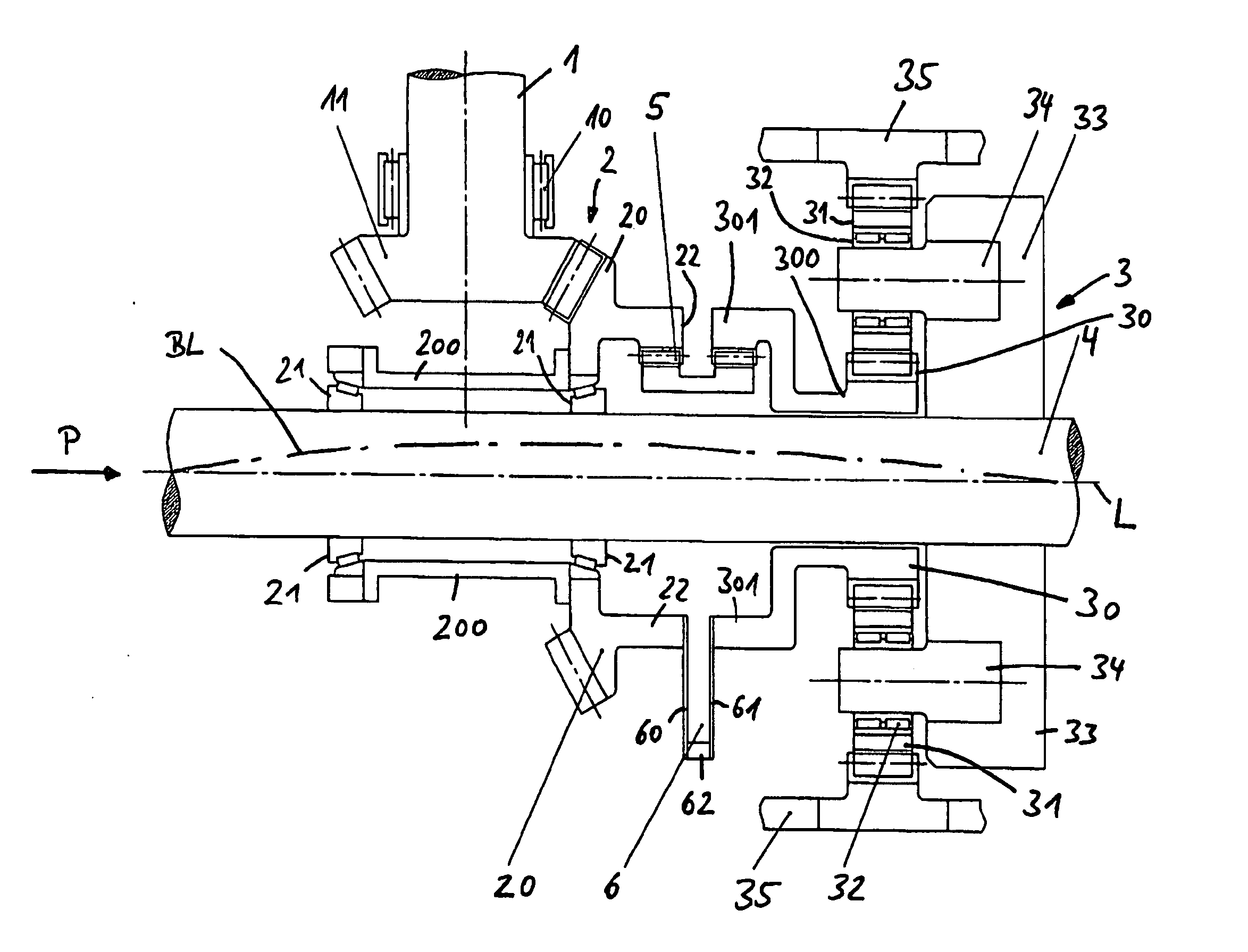
Figure 1 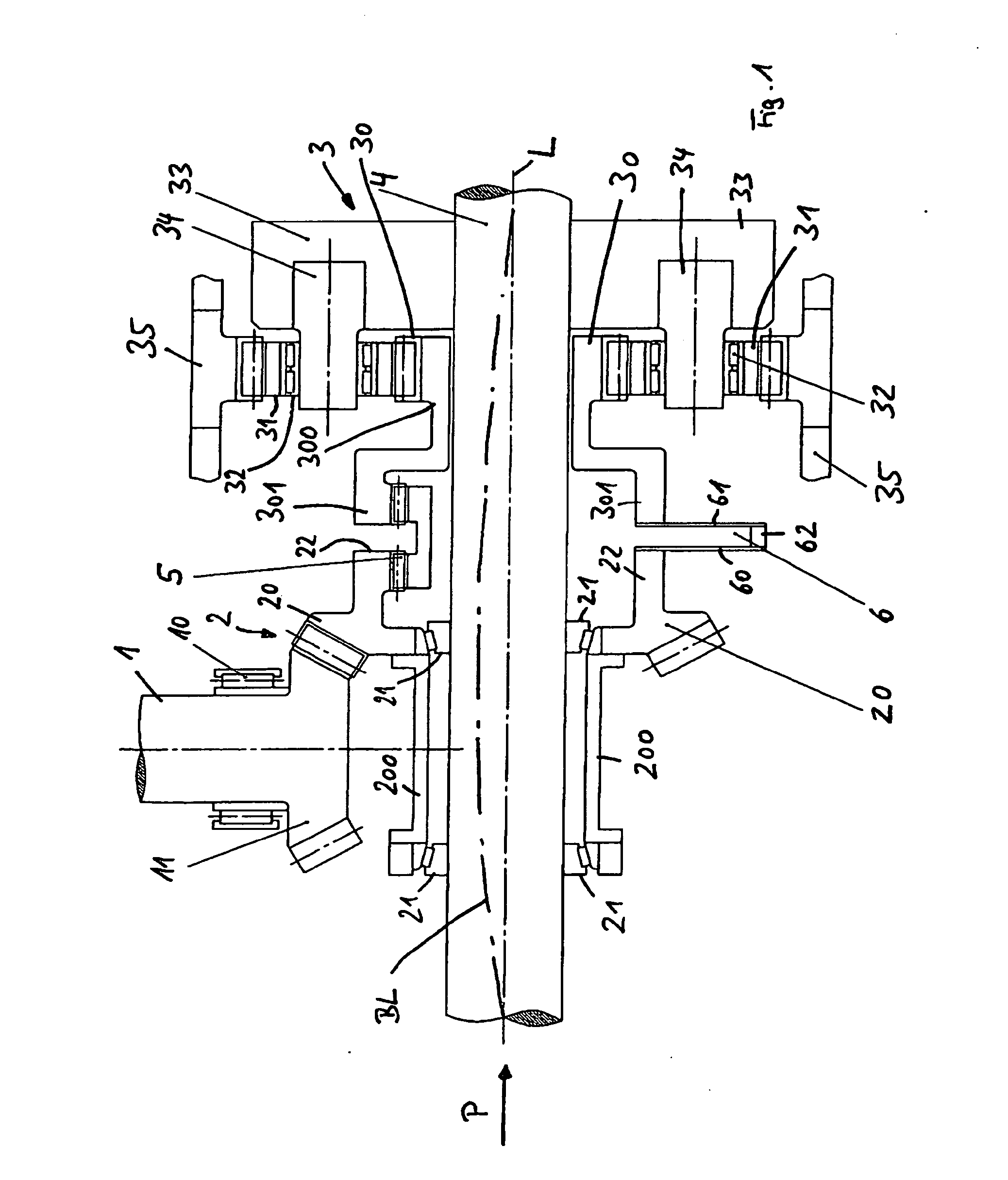
Figure 2 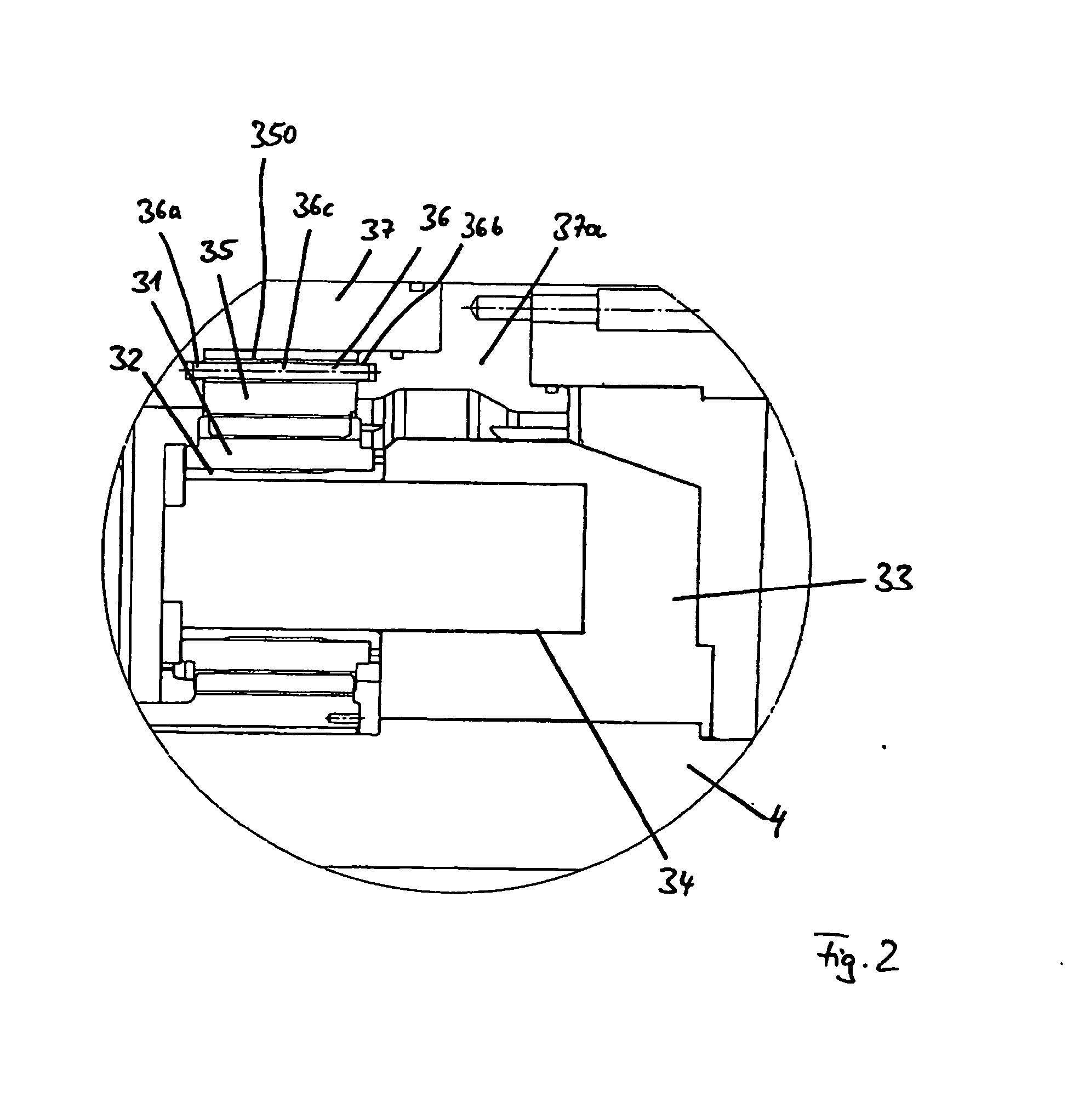
Figure 3
Abstract
Description
BACKGROUND OF THE INVENTION
[0001] 1. Field of the Invention
[0002] This invention relates to a rudder propeller with a drive shaft and a propeller shaft that can be driven by the drive shaft by an angular drive and a planetary gearing, the planetary gearing can be situated on the propeller shaft and include a sun gear connected to the angular gear by a coupling, a stationary ring gear, and planet gears that are mounted on a planet carrier and travel between the sun gear and the ring gear, and the planet carrier can be mounted to the propeller shaft in a torsionally rigid fashion.
[0003] 2. Discussion of Related Art
[0004] Rudder propellers of the type mentioned above are known, for example, from German Patent Reference DE 28 43 459 A1. The rudder propeller is used to drive and steer a watercraft. The motor torque of a drive motor, which is usually situated inside the watercraft, is transmitted via a vertically extending drive shaft and an angular drive, which has a planetary gearing connec...
Examples
Embodiment Construction
[0018]FIG. 1 shows the drive of a rudder propeller of an intrinsically known design in a schematic view showing only parts of an overall mechanism. The basic drive principle is known, for example, from German Patent Reference DE 28 43 459 A1, the entire description of which is included in this specification by reference.
[0019]Element reference numeral 1 indicates a vertically extending drive shaft 1 that extends down through or out of a hull and is set into rotation by a drive motor that is not shown in detail. The drive shaft 1 is supported by a pivot bearing 10 and at its end, has a pinion 11, which is a component of an angular drive 2 that is explained in greater detail below.
[0020]Element reference numeral 4 indicates a propeller shaft, which extends at right angles to the drive shaft 1 and, in a manner not shown in detail, supports a propeller for propulsion of the watercraft at its left end in the drawing of FIG. 1.
[0021]The drive motor, not shown, rotates the drive shaft 1 to...