
Dosimeter, therapeutic apparatus, and computer program product for measuring radiation dosage to a subject during magnetic resonance imaging
Patent Information
- Authority / Receiving Office
- US · United States
- Current Assignee / Owner
- Publication Date
- 2013-08-22
Smart Images
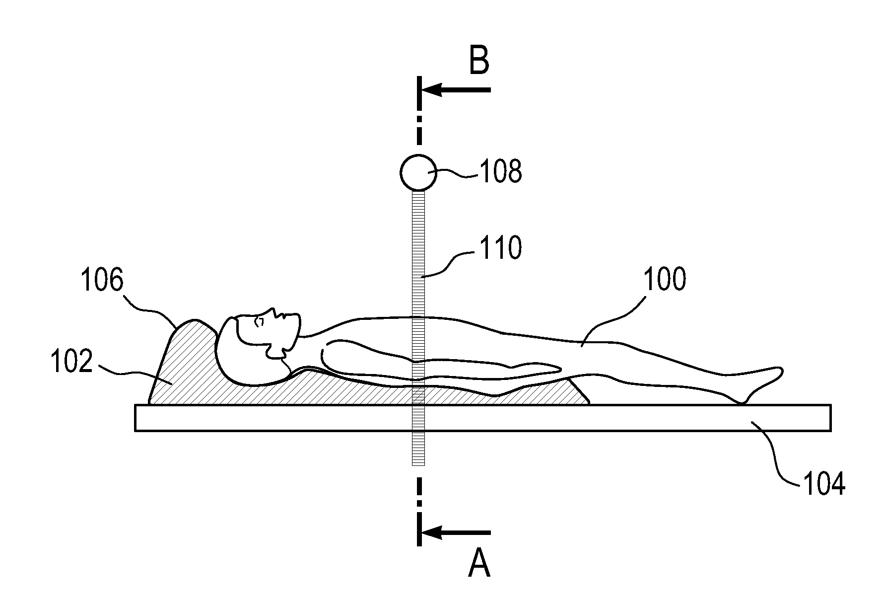
Figure 1 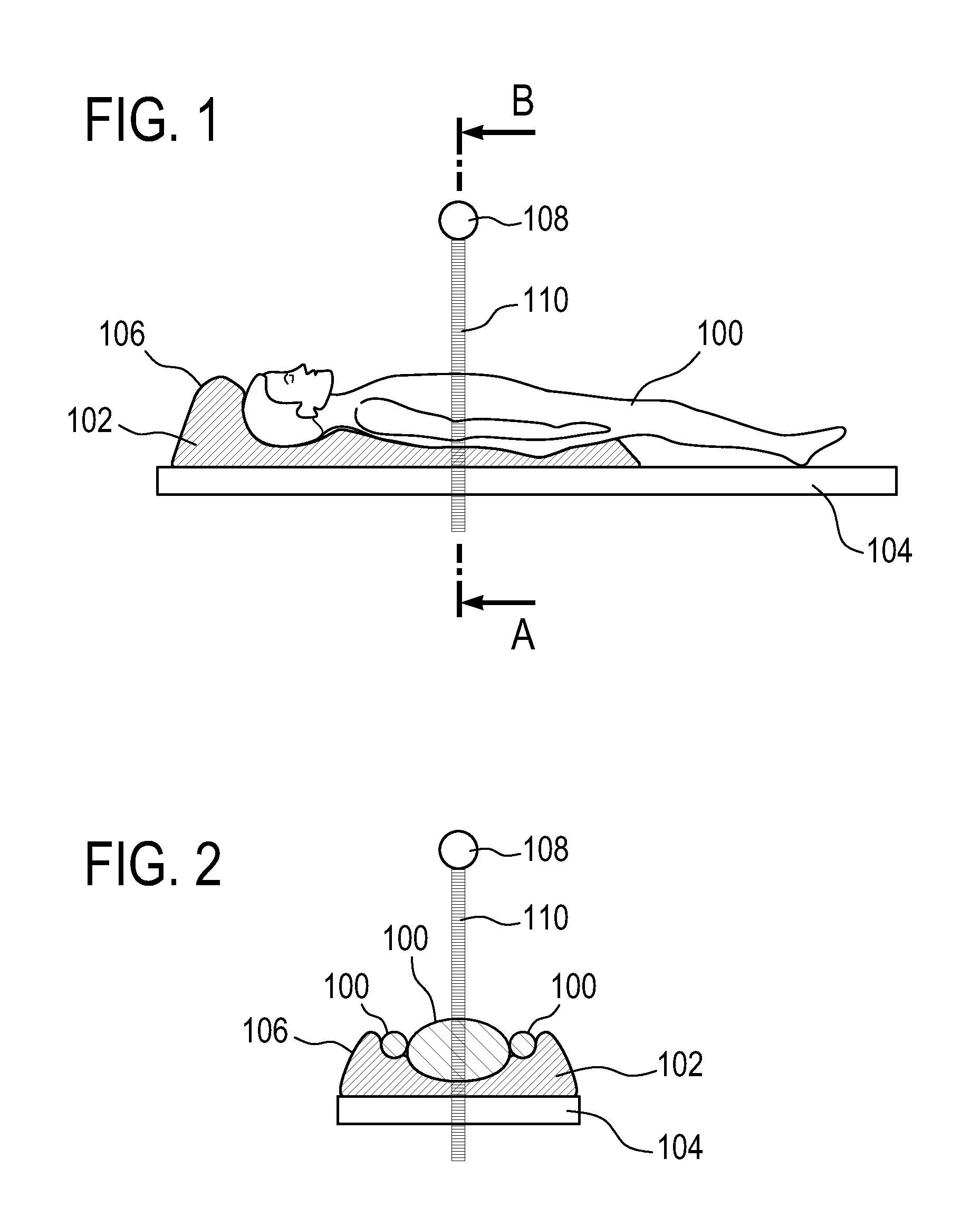
Figure 2 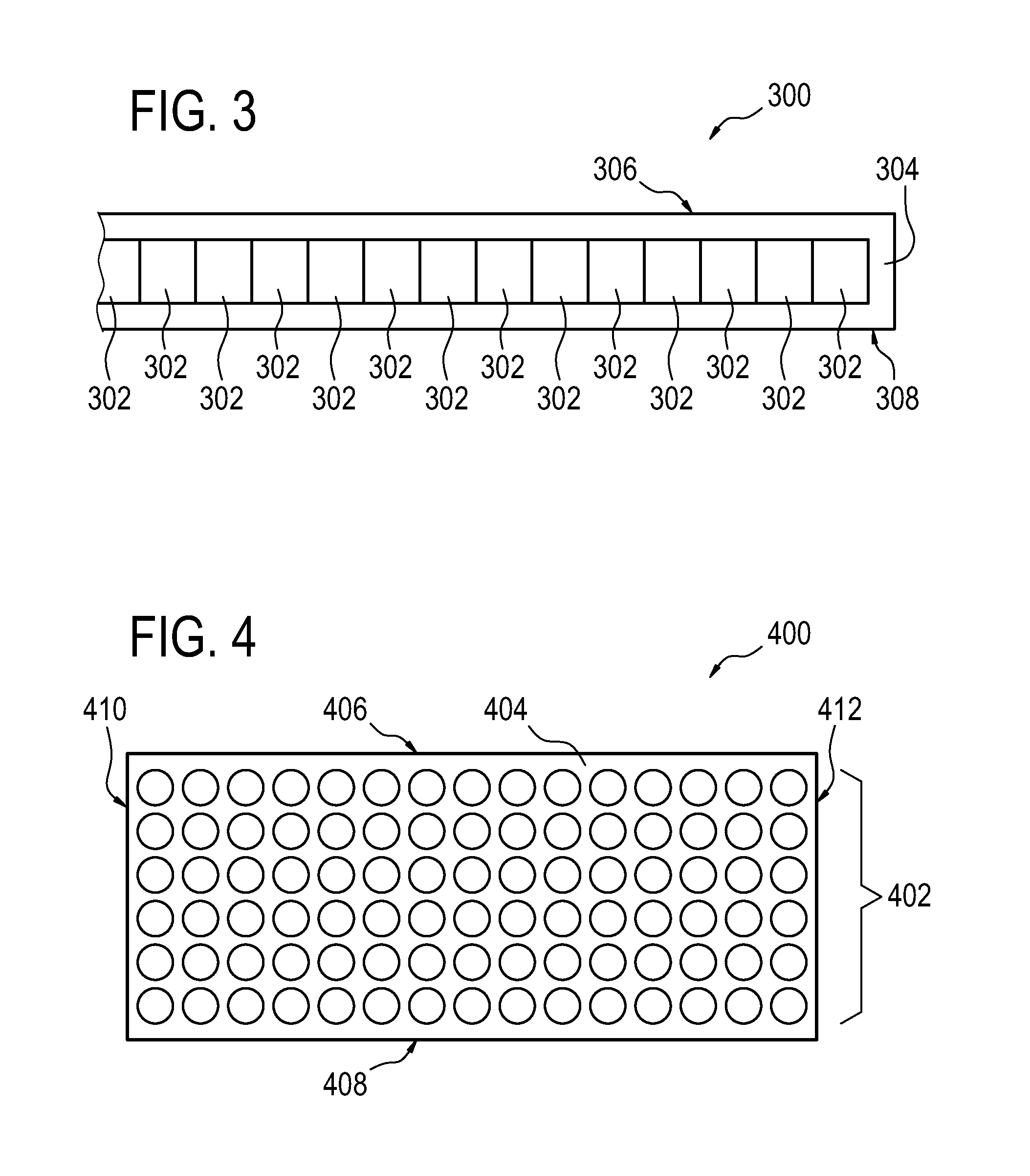
Figure 3
Abstract
Description
TECHNICAL FIELD
[0001] The invention relates to radiation dosimetry, in particular to radiation dosimetry during magnetic resonance imaging.BACKGROUND OF THE INVENTION
[0002] During radiotherapy (RT) treatments the radiation beam has to be focused on a well-defined target region and its dose has to be precisely controlled. To verify the accuracy of the radiotherapy treatment field relative to the patient, radiosensitive film, video vision systems, ion chambers and electronic portal imaging devices (EPIDs) are currently used for two-dimensional (real-time) monitoring of the applied dose. Additionally time-consuming regular quality assurance of (three-dimensional) radiation dose distribution has to be performed with specific phantoms.
[0003] Some of the relevant characteristics of currently used radiation treatment field verification / dosimetry techniques are:
[0004] Ion chamber (low resolution, slow, non-integrating dose measurement),
[0005] Video chain (cumbersome, not geometrically accurate, ...
Examples
Embodiment Construction
[0072]Like numbered elements in these figures are either equivalent elements or perform the same function. Elements which have been discussed previously will not necessarily be discussed in later figures if the function is equivalent.
[0073]FIGS. 1 and 2 are used to illustrate the usage of a dosimeter according to an embodiment of the invention. FIG. 1 shows a side view of a subject reposing on a subject support 104. There is a dosimeter 102 between the subject and the subject support 104. The dosimeter 102 is in the form of a vacuum pillow or cushion for the subject 100 to repose upon. FIG. 2 is identical to that of FIG. 1 except in FIG. 2 a cross-section of the line marked AB in FIG. 1 is shown in FIG. 2. The dosimeter 102 is shown as having an outer thermal insulation layer 106 which thermally isolates the dosimeter 102 from the subject 100. Along the cross-section line AB there is a radiation source 108 which generates a beam of ionizing radiation 110. The ionizing radiation 110 ...