
Balanced-to-unbalanced transformer
a transformer and unbalance technology, applied in the direction of coils, waveguides, coupling devices, etc., can solve the problems of relatively expensive production of relativly bulky arrangements, unbalanced transformers constructed in printed circuit technology, etc., and achieve the effect of easy and inexpensive production in printed circuit technology
Patent Information
- Authority / Receiving Office
- US · United States
- Patent Type
- Patents(United States)
- Current Assignee / Owner
- Publication Date
- 2005-07-12
- Estimated Expiration
- Not applicable · inactive patent
Smart Images
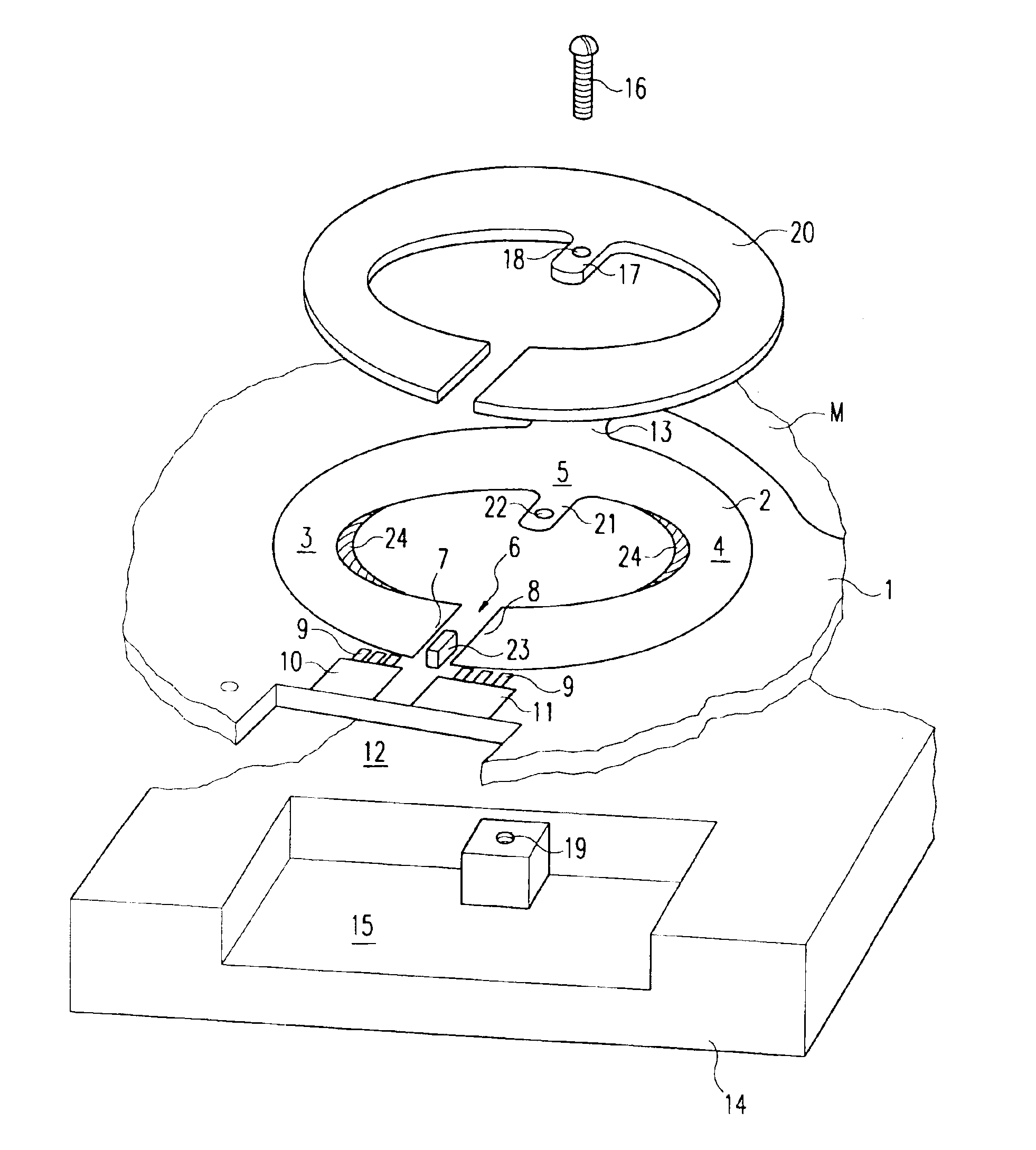
Figure 1 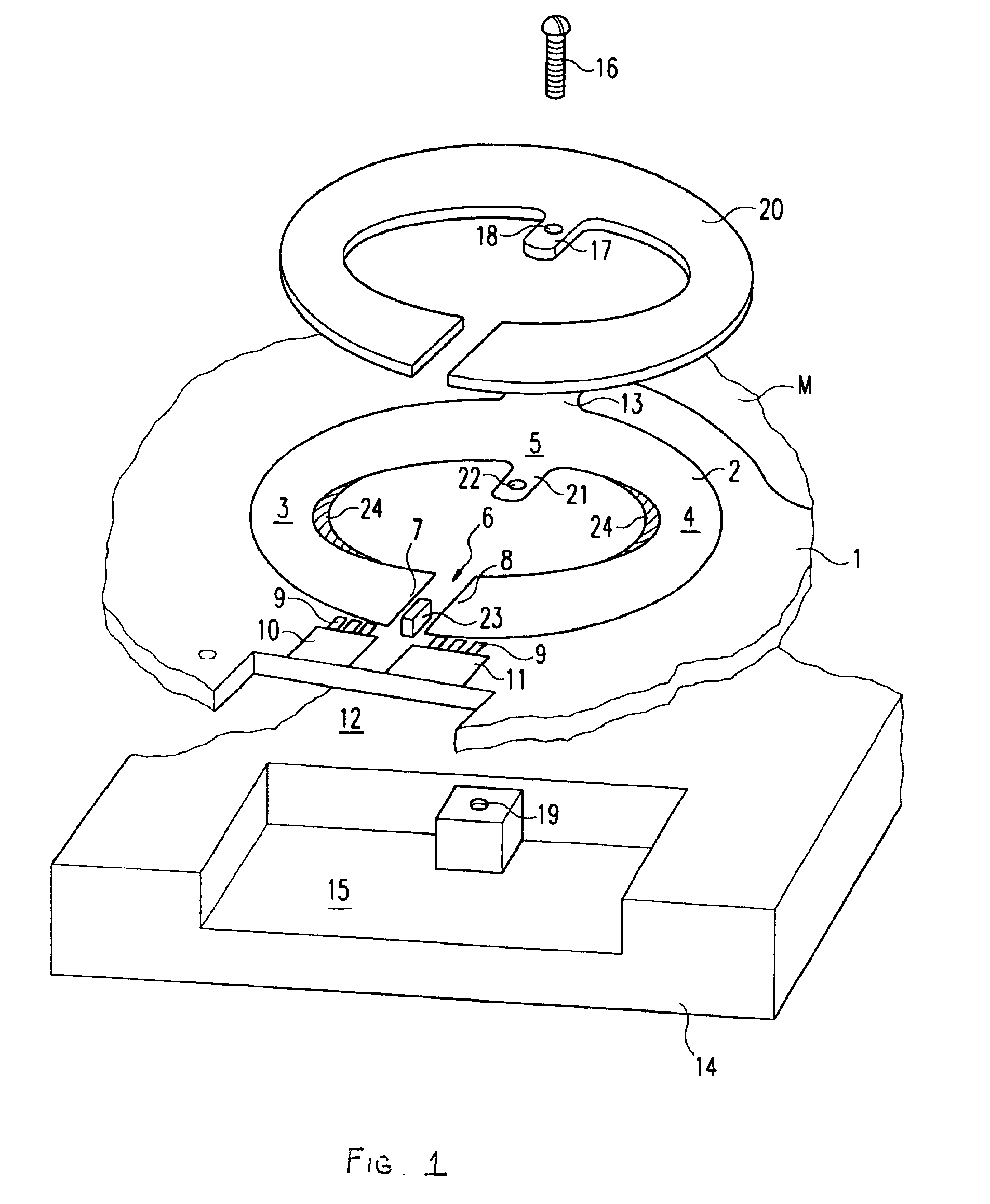
Figure 2
Abstract
Description
[0001] This application is the national phase under 35 U.S.C. §371 of PCT International Application No. PCT / EP02 / 000146 which has an International filing date of Jan. 2, 2002, which designated the United States of America and which claims priority on Germany Patent Application number 101 05 696.6 filed Feb. 8, 2001, the entire contents of which are hereby incorporated herein by reference.FIELD OF THE INVENTION
[0002] The invention relates to a balanced-to-unbalanced transformer (BALUN) for transmitting large high-frequency power, for example at the balanced output of a transistor power amplifier for coupling to an unbalanced output line.BACKGROUND OF THE INVENTION
[0003] Balanced-to-unbalanced transformers for higher powers have hitherto been constructed in coaxial line technology. This results in relatively bulky arrangements that have to be relatively expensively produced manually and connected as separate components to the rest of the circuit.
[0004] It is also already known to produce ...
Examples
Embodiment Construction
[0013]FIG. 1 illustrates a portion of a push-pull transistor power amplifier that is formed in printed circuit technology on a conductor board 1 shown in fragment form and whose balanced output is connected to a conductor loop 2, balanced with respect to ground M, of a balanced-to-unbalanced transformer. Said balanced conductor loop 2 has the shape of a circular ring pressed together from opposite sides and having two opposite C-shaped loop halves 3 and 4 that merge into one another integrally on the one side at 5 and form a slot 6 on the opposite side. Two opposite ends 7 and 8, forming the slot 6, of the C-shaped loop halves 3 and 4 form the balanced input of the balanced-to-unbalanced transformer, and they are electrically connected via transformer capacitors 9 to conductor tracks 10 and 11 with which the terminal lugs of the high-frequency power transistor, which is not shown and which is inserted in the rectangular recess 12, make contact.
[0014]The input circuit for the power t...