
Centrifuge
A centrifuge and guide rod technology, applied in the field of centrifuges, can solve the problems of high price and cost, and achieve the effects of low production cost, simple principle and structure, and stable equipment
Patent Information
- Authority / Receiving Office
- CN · China
- Current Assignee / Owner
- Publication Date
- 2014-09-03
- Estimated Expiration
- Not applicable · inactive patent
Smart Images
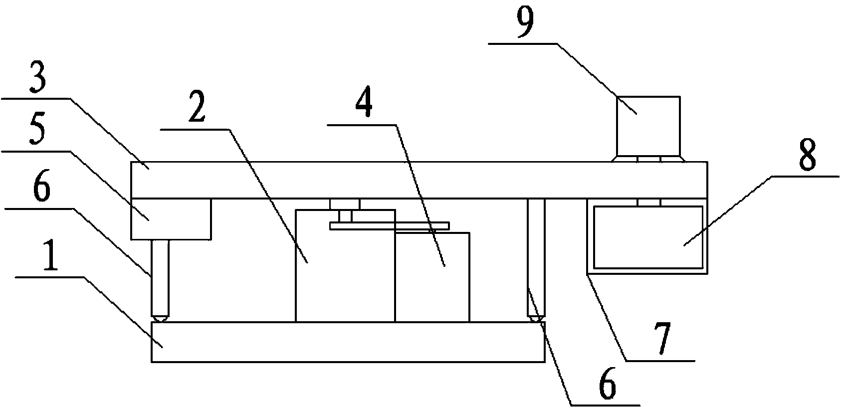
Figure 1 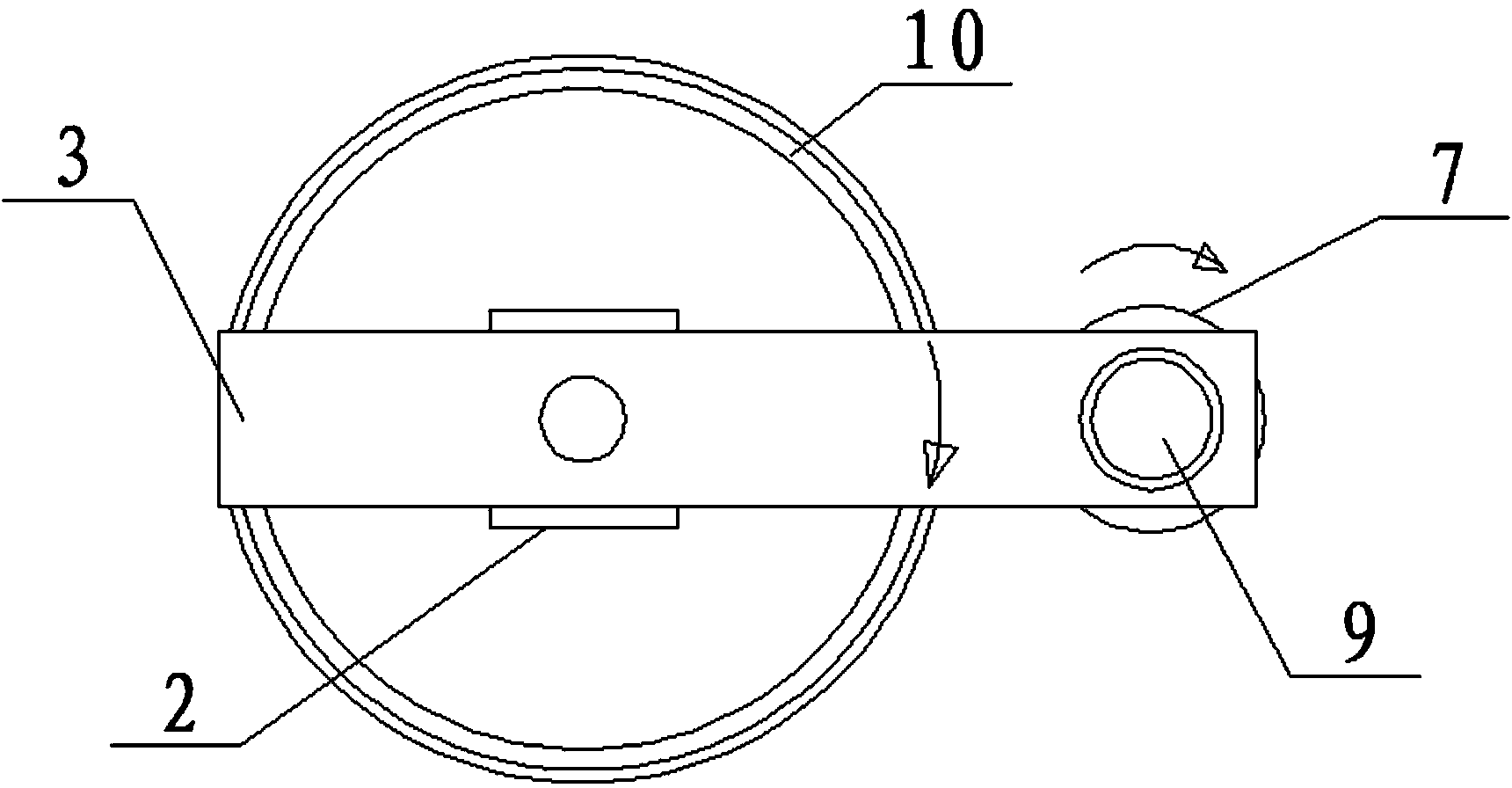
Figure 2
Abstract
Description
technical field
[0001] The invention relates to the technical field of centrifuges, in particular to a centrifuge. Background technique
[0002] A centrifuge is a separation machine whose function is to separate the mixture of solid and liquid (liquid and liquid) to obtain solid and liquid (or liquid and liquid) respectively. What is its working principle? We all know that when a mixture of different densities is left to stand, natural stratification will occur, and the solids will generally settle to the bottom layer, while the upper layer will form a clear liquid. Most of the existing separation machines use a motor to drive the drum to rotate, and increase the speed by increasing the motor's ability. Due to the restriction of the motor technology, the speed is limited to a certain extent. At the same time, the price and cost of the high-speed motor are relatively high, so an ordinary motor is needed first. A centrifuge with relatively high speed operation can be achieved...
Examples
Embodiment Construction
[0013] Referring to the accompanying drawings, a centrifuge includes a bottom plate 1 and a rotating base 2. It is characterized in that: the rotating base 2 is provided with a rotating guide rod 3, and the rotating guide rod 3 is connected to the motor located on the side of the rotating base 2 through a belt. one 4
[0014] Above, the end of one side of the rotating guide rod 3 is provided with a counterweight 5, the bottom of the counterweight 5 is provided with a supporting structure 6, the other end of the rotating guide rod 3 is provided with a drum 8, and the rotating The drum 8 is connected to the motor 2 9 positioned above the rotating guide rod, and the other side of the rotating guide rod 3 is provided with a supporting structure 6; the described base plate 1 is a circular structure, and the described base plate 1 is provided with a The structure 6 slides the annular track 10;: the support structure 6 is a support rod, and the bottom of the support rod is provided w...