
Film and television high-speed camera equipment
A high-speed camera and film and television technology, which is applied to mechanical equipment, televisions, supporting machines, etc., to achieve the effect of convenient debris handling and stable equipment
Patent Information
- Authority / Receiving Office
- CN · China
- Current Assignee / Owner
- Publication Date
- 2021-07-30
Smart Images
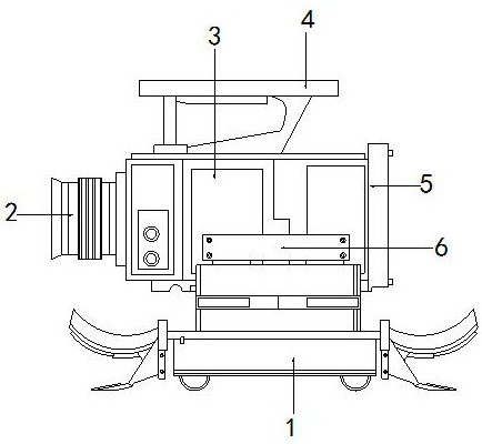
Figure 1 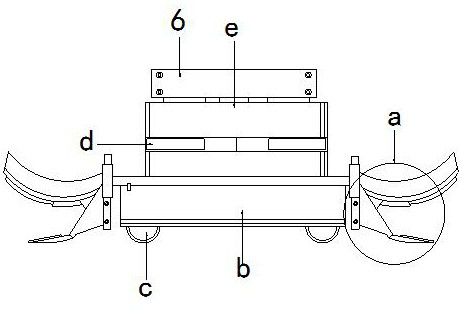
Figure 2 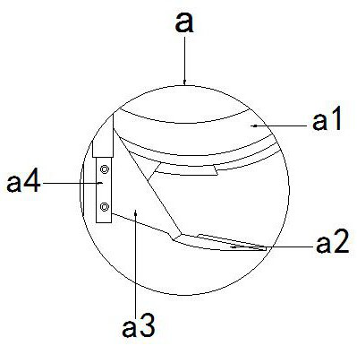
Figure 3
Abstract
Description
technical field
[0001] The invention is a high-speed video camera equipment, which belongs to the field of photography equipment. Background technique
[0002] A high-speed video camera is a device capable of capturing moving images with an exposure of less than 1 / 1000 of a second or a frame rate exceeding 250 frames per second, and it is used to record fast-moving objects as photographic images on a storage medium, and it is also applied In film and television shooting, in the process of film and television shooting and creation, slide rails will be installed at the bottom to ensure the stability of shooting.
[0003] The existing technology has the following disadvantages: when the camera equipment is moving and shooting, the bottom guide rail is not easy to clean because of its narrow environmental factors, and some small stones and other debris will be mixed in, and it is easy to produce bumps during the shooting and sliding process In some cases, the pulley block may b...
Examples
no. 1 example
[0026] see Figure 1-Figure 3 , the present invention provides a technical solution for high-speed video camera equipment: its structure includes: a rail frame device 1, a lens module 2, a main body 3, a holding frame 4, an interface end plate 5, and a connecting horizontal plate 6. The frame 4 is installed on the top of the main body 3 and locked with the main body 3, the front end of the main body 3 is provided with a lens module 2, the lens module 2 is screwed with the main body 3, and the rear side of the main body 3 is provided with a There is an interface end plate 5, the interface end plate 5 is locked with the main body 3, the side of the main body 3 is provided with a connecting horizontal plate 6 and is locked with the connecting horizontal plate 6, and the bottom of the connecting horizontal plate 6 is provided with Track frame device 1, said track frame device 1 is buckled with connecting horizontal plate 6, said track frame device 1 includes scraper body a, fixed ...
no. 2 example
[0030] see Figure 4-Figure 6 , the present invention provides a technical solution for high-speed video camera equipment: its structure includes: the adsorption plate device a1 includes an adsorption groove device a11, an adjustment bar a12, a docking buckle plate a13, and an arc plate a14, and the adsorption groove device a11 is installed on The bottom of the arc plate a14 is buckled with the arc plate a14, the side of the arc plate a14 is provided with a docking plate a13, the inner side of the adsorption tank device a11 is provided with an adjustment bar a12, and the adjustment bar a12 is connected with the adsorption tank device a11 buckle.
[0031] The suction groove device a11 includes a fixed frame a111, a magnetic strip a112, and a spliced suction piece a113. The spliced suction piece a113 is installed on the side of the magnetic strip a112 and fastened with the magnetic strip a112. Box a111.
[0032] The contact plate device a2 includes a sliding section a21, a...