
Mining roadway grooving machine
A slotting machine and roadway technology, applied in the direction of slitting machinery, propulsion, driving devices, etc., to achieve the effect of ensuring project quality, reducing link costs and speeding up construction
Patent Information
- Authority / Receiving Office
- CN · China
- Current Assignee / Owner
- Publication Date
- 2022-01-14
Smart Images
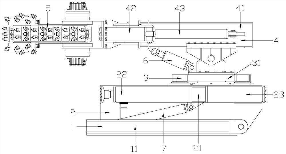
Figure 1 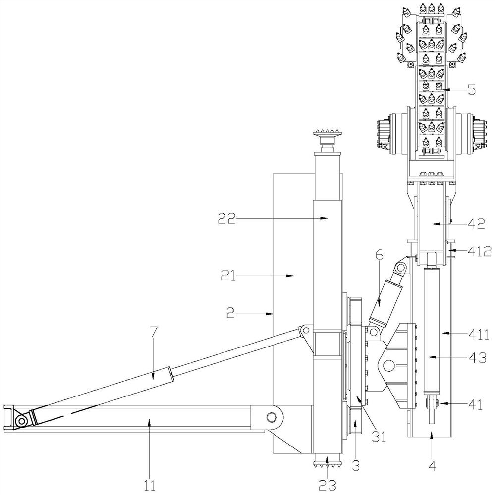
Figure 2 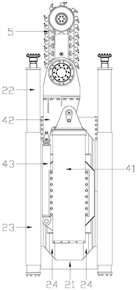
Figure 3
Abstract
Description
Technical field:
[0001] The invention relates to underground mining equipment, in particular to a mining roadway slotting machine. Background technique:
[0002] Coal is the cornerstone of my country's energy security and is of great importance to national economic security. The occurrence conditions of coal seams in my country are various, including medium-thick coal seams and thin coal seams, and the mining conditions are different. There are great differences in the mining scale, technical equipment and mining methods of coal mines in different regions.
[0003] Thin coal seams account for a large proportion of the current proven reserves. Since the thin coal seam brings greater difficulty to mining, all the downhole equipment must be miniaturized. At present, the existing slotting machines in China are not suitable for slotting operations in thin coal seam roadways. Temporary building of wind walls, slotting of permanently sealed walls, digging of water pump nests in j...
Examples
Embodiment
[0019] Example: such as Figure 1 to Figure 4 As shown, the mining roadway slotting machine includes a fixed base 1, an overturned base 2, a rotary drive 3, a cantilever 4, and a milling head 5; the overall fixed base 1 includes two parallel fixed beams 11, A connecting beam 12 is fixed between one end of the two fixed beams 11; the flip base 2 includes a mouth-shaped flip frame 21, and a top hydraulic cylinder 22 and a leg hydraulic cylinder 23 are respectively fixed on both sides of the flip frame 21. Be provided with two double-rod hydraulic cylinders 24 shown in parallel with the fixed beam 11 in the flip frame 21, the piston rod of the double-rod hydraulic cylinder 24 is fixedly connected with the flip frame 21; the bottom surface of the flip frame 21 is hinged with the fixed beam 11; An overturning hydraulic cylinder 7 is arranged between the overturning frame 21 and the fixed base 1, the cylinder barrel of the overturning hydraulic cylinder 7 is hinged with the fixed ba...