
Vapor-liquid two-phase flow simulation system and simulation method for shell-and-tube steam generator
A technology of steam generator and simulation system, which is applied in steam generation methods, instruments, boiler water pipes, etc. using heat carrier, and can solve the problems that the gas-liquid two-phase pipe flow cannot be truly simulated and accurately measured, so that the test results are true and reliable , Guarantee the sealing condition, simplify the effect of the test system structure
Patent Information
- Authority / Receiving Office
- CN · China
- Patent Type
- Patents(China)
- Current Assignee / Owner
- Publication Date
- 2016-05-04
- Estimated Expiration
- Not applicable · inactive patent
Smart Images
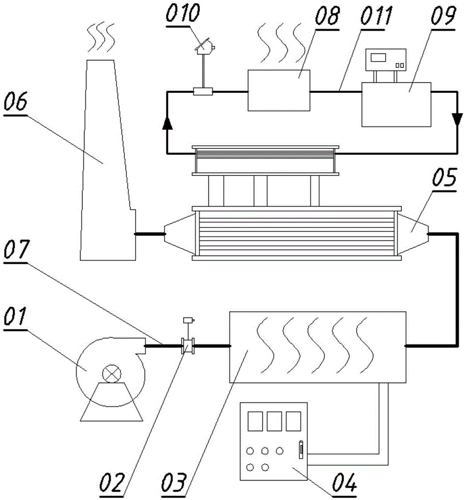
Figure 1 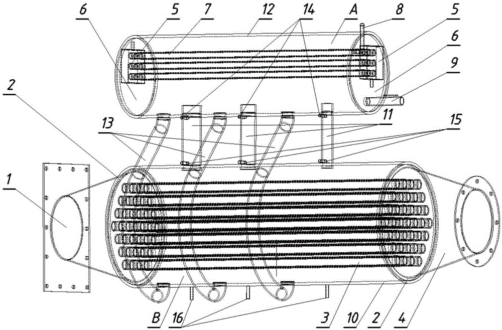
Figure 2
Abstract
Description
technical field
[0001] The invention belongs to the technical field of flue gas waste heat utilization equipment and methods, and in particular relates to a vapor-liquid two-phase flow simulation system and simulation method for a shell-and-tube steam generator. Background technique
[0002] As an important technical means of waste heat recovery, the shell and tube steam generator has been widely used all over the world. For example: metallurgical furnaces, heating furnaces, industrial kilns, fuel gasification devices, etc., all have a large demand for waste heat utilization, but the shell-and-tube steam generator plays an extremely important role. However, due to the high temperature of high-temperature flue gas in the tube side of the waste heat steam boiler and the large flow rate, the high-temperature gas directly scours the weld seam between the heat exchange tube and the tube sheet, which will easily lead to high-temperature oxidation and cracking and leakage at the co...
Examples
Embodiment 1
[0077] The shell-and-tube steam generator vapor-liquid two-phase flow simulation system includes an open-loop air system and a closed-loop water system. The open-loop air system includes an open-loop air system and a closed-loop water system; the open-loop air system includes a The air duct 07 is sequentially connected to the frequency conversion fan 01, the flow meter 02, the electric heating box 03, the evaporator B in the simulation device 05, and the exhaust gas treatment equipment 06. The frequency conversion fan 01 is connected to one end of the air duct 07, and the flow meter 02 is set on the Between the fan 01 and the electric heating box 03, the air outlet of the electric heating box 03 is connected to the air inlet of the evaporator B, and the air outlet of the evaporator B is connected to the tail gas treatment equipment 06 The tail gas treatment equipment 06 is connected to the other end of the air duct 07 ;The closed-loop waterway system is composed of the high-tem...
Embodiment 2
[0081] The simulation device 05 includes a condenser A and an evaporator B arranged in parallel below the condenser A, and the condenser A and the evaporator B are airtightly connected by an ascending tube group 11 and a descending tube group 13 .
[0082] Condenser A includes a transparent condenser shell 12, which is a horizontally arranged cylinder, and the inner sides of the two opposite ends of the transparent condenser shell 12 are embedded and sealed with small tube sheets 6, transparent Condenser tube bundles 7 are horizontally arranged in the condenser shell 12, and the two ends of the condenser tube bundles 7 are respectively welded to the small tube sheets 6 on both sides. The small tube plate 6 on the side is also welded with an air port 8 and a water inlet interface 9 respectively.
[0083] The evaporator B includes a transparent evaporator shell 10, which is a cylinder arranged horizontally, and a large tube plate 2 is embedded and sealed inside the opposite left...
Embodiment 3
[0087] According to the research needs, the sealed evaporator B and the sealed condenser A with a certain tube arrangement, tube outer diameter and tube spacing are passed through a certain size and tube type of riser tube group 11 and down tube group 13 sealant use PIV to measure the velocity field distribution characteristics of the shell-side vapor-liquid two-phase flow of the simulation device, use a high-speed camera to record the flow pattern of the shell-side vapor-liquid two-phase flow of the simulation device, and use an infrared thermal imager to measure the simulation For the temperature gradient of the heat exchange tube bundle 3 of the device, use a pressure measuring instrument to measure the pressure drop between the pressure measuring port 1# group 16, the pressure measuring port 2# group 15 and the pressure measuring port 3# group 14 of the simulation device; According to the research needs, the temperature and flow rate of the hot air entering the evaporator B...