
A compressor silencer
A compressor and noise reduction technology, which is applied in the direction of machines/engines, mechanical equipment, liquid variable displacement machinery, etc., can solve the problems that affect the sound resistance performance and service life, uneven air flow distribution, and damage to resistive noise reduction parts. Achieve the effect of increasing the maximum gas passing capacity, reducing the gas passing resistance and preventing local damage
Patent Information
- Authority / Receiving Office
- CN · China
- Patent Type
- Patents(China)
- Current Assignee / Owner
- Publication Date
- 2016-03-23
Smart Images
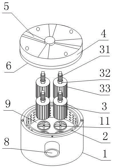
Figure 1 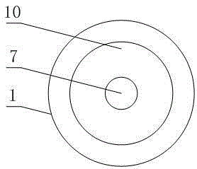
Figure 2 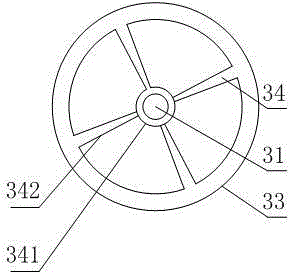
Figure 3
Abstract
Description
technical field
[0001] The invention relates to an air compressor noise reduction device, in particular to a compressor noise reduction mechanism. Background technique
[0002] An air compressor is a device used to compress gas. Most air compressors are reciprocating pistons, rotating blades or rotating screws, which convert the mechanical energy of the prime mover (usually an electric motor) into gas pressure energy. Widely used in petroleum, chemical and food manufacturing industries.
[0003] The air compressor is a typical large-scale power equipment, and the intake noise is an important source of its noise, especially in the reciprocating piston compressor, at the suction port of the cylinder, the sound wave is radiated from the intake port in the form of pulsating changes . In the prior art, the muffler applied to the air inlet of the compressor mostly adopts an impedance compound muffler, and the muffler for the noise of the air inlet can reach 30 decibels or more. ...
Examples
Embodiment 1
[0026] Such as figure 1 , a compressor muffler mechanism provided by the present invention comprises a barrel-shaped lower housing 1, an upper cover 4 is fixedly connected to the beginning end of the lower housing 1, and the upper cover 4 and the lower housing 1 enclose a muffler cavity 9 , the muffler cavity 9 is provided with a resistive muffler, the upper cover 4 or the lower housing 1 is also provided with an air outlet 7 and an air inlet 8 communicating with the muffler cavity 9, and also includes a cylindrical shape with multiple side walls. An inner cylinder 2 with a through hole, one end of the inner cylinder 2 is fixed on the bottom of the lower casing 1, the resistive noise-absorbing part includes a plurality of noise-absorbing barrels 3, the sound-absorbing barrels 3 are in the shape of a barrel with an open lower end, and its side is provided with A plurality of strip-shaped ribs 33 parallel to its axial direction, the left and right sides of the strip-shaped ribs ...
Embodiment 2
[0029] This embodiment is further limited on the basis of embodiment 1: as figure 1, the top of the sound-absorbing barrel 3 is provided with an internally threaded through hole, and a connecting screw 31 threadedly connected thereto is arranged in the internally threaded through-hole, and the upper and lower ends of the connecting screw 31 protrude respectively relative to the upper and lower ends of the sound-absorbing barrel The connecting screw 31 on the outside of the top of the sound-absorbing barrel 3 is provided with a nut 32 threadedly connected with the connecting screw 31. The sound-absorbing barrel interface 11 is a hole-like structure that runs through the bottom of the lower housing 1, and the hole-like structure is provided with The two ends of the rib connected with its inner wall are provided with a connecting screw hole, and the lower end of the connecting screw 31 is threadedly connected with the connecting screw hole.
[0030] The intersection of the hole s...
Embodiment 3
[0033] This embodiment is further limited on the basis of embodiment 1: as figure 1 and image 3 , the lower end of the sound-absorbing barrel 3 or its inner wall is provided with at least one rigidity cage 34 parallel to the radial direction of the sound-absorbing barrel 3, and the rigidity cage 34 includes a circular tube 341 and at least two connecting bars 342 , the two ends of the connection bar 342 are fixedly connected with the sound-absorbing bucket 3 and the circular pipe 341 respectively, and the connecting strips 342 are evenly distributed in a ring shape, the connecting screw 31 and the circular pipe 341 form a clearance fit, and the lower end of the sound-absorbing bucket 3 is still A sealing ring is provided.
[0034] In the above settings, there are gaps between adjacent connecting bars 342 for the circulation of gas in the inner cavity of the sound-absorbing bucket 3, and the circular tube 341 provided is used to reduce the span between the fulcrums of the con...