
Volume cavity regulating type exhausting device
A cavity-adjustable, volume-adjustable technology, applied in machines/engines, internal-combustion piston engines, mechanical equipment, etc., can solve problems such as the complex structure of the booster system, and achieve the effects of low fuel consumption, large air intake, and simple structure
Patent Information
- Authority / Receiving Office
- CN · China
- Patent Type
- Applications(China)
- Current Assignee / Owner
- Publication Date
- 2015-07-15
- Estimated Expiration
- Not applicable · inactive patent
Smart Images
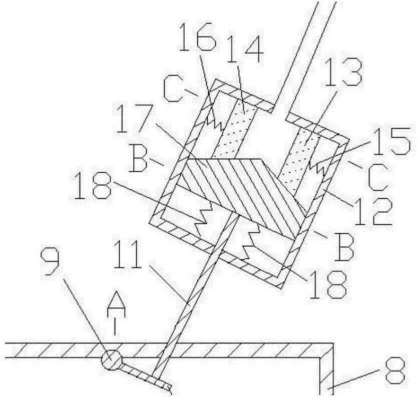
Figure 1 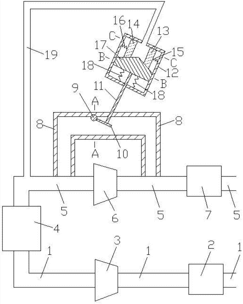
Figure 2 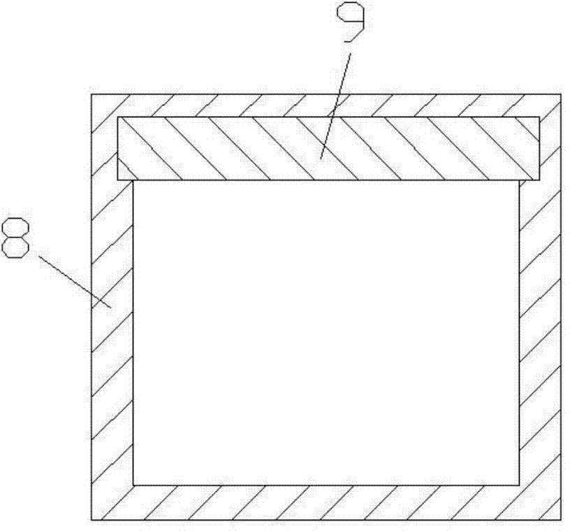
Figure 3
Abstract
Description
technical field
[0001] The invention belongs to the technical field of internal-combustion engine design, in particular to a volume cavity-adjustable gas-bleeder capable of realizing self-regulation of turbine deflation. Background technique
[0002] Turbocharging is a technology that uses the exhaust gas generated by the operation of an internal combustion engine to drive an air compressor. The main function of turbocharging is to increase the air intake of the engine, thereby increasing the power and torque of the engine and making the car more powerful. After an engine is equipped with a turbocharger, its maximum power can be increased by 40% or even higher compared with that without a supercharger. This also means that the same engine can output more power after being supercharged. Take our most common 1.8T turbocharged engine as an example. After supercharging, the power can reach the level of a 2.4L engine, but the fuel consumption is not much higher than that of a 1...
Examples
Embodiment
[0015] Examples of the present invention are Figure 1 to Figure 5 As shown, the present invention includes intake pipe 1, air filter 2, compressor 3, engine 4, exhaust pipe 5, turbine 6, muffler 7, air release pipe 8, rotating shaft 9, rotating plate 10, adjusting rod 11, control Cavity 12, first moving body 13, second moving body 14, first spring 15, second spring 16, third moving body 17, third spring 18, control pipe 19, air intake of engine 4 and air intake pipe 1 The air inlet and outlet of the exhaust pipe 5 are connected to the air outlet of the engine 4, the air filter 2 and the compressor 3 are connected to the intake pipe 1 in turn, the turbine 6 and the muffler 7 are connected to the exhaust pipe 5 in turn Above, the two ends of the air discharge pipe 8 are respectively connected with the exhaust pipes 5 before and after the turbine 6, the rotating shaft 9 is inlaid on the air discharging pipe 8, the rotating plate 10 is arranged in the air discharging pipe 8 and o...