
Chargeable electric equipment
An electrical equipment and rechargeable technology, which is applied to electrical components, battery circuit devices, and structural components of conversion equipment, etc., can solve the problem of increased power consumption of rechargeable electrical equipment, save power and reduce battery power consumption. Effect
Patent Information
- Authority / Receiving Office
- CN · China
- Current Assignee / Owner
- Publication Date
- 2016-03-09
Smart Images
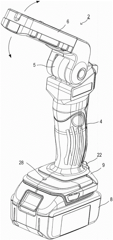
Figure 1 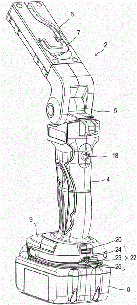
Figure 2 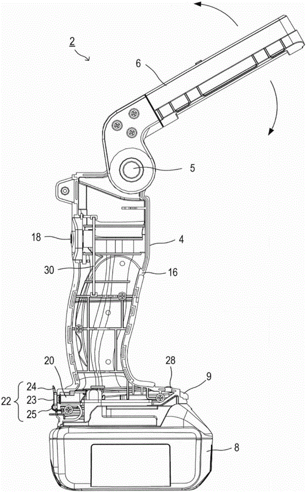
Figure 3
Abstract
Description
technical field
[0001] The present invention relates to a rechargeable electric device that operates by receiving power supply from a rechargeable and dischargeable battery. Background technique
[0002] Conventionally, there is known a rechargeable lamp that detachably mounts a battery pack containing a rechargeable and dischargeable battery and receives power from the mounted battery pack to turn on the lamp (for example, refer to Patent Document 1).
[0003] In addition to rechargeable lamps, various electric devices such as rechargeable electric tools, vacuum cleaners, gardening tools (lawn mowers, etc.), radios, etc. are known as rechargeable electric devices that receive power supply from a battery and operate.
[0004] Patent Document 1: Japanese Unexamined Patent Application Publication No. 2013-70504
[0005] Such rechargeable electrical equipment is equipped with a battery that can be charged and discharged, so it is considered to use this battery to supply power ...
Examples
Embodiment Construction
[0034] The following is attached Figure 1 Embodiments of the present invention will be described first.
[0035] Such as Figure 1 ~ Figure 3 As shown, the rechargeable lamp 2 of this embodiment includes a rod-shaped grip portion 4 that can be gripped by the user, a lamp portion 6 provided on one end side of the grip portion 4 in the longitudinal direction, and a lamp portion detachably attached to the grip portion. The battery pack 8 on the other end side in the longitudinal direction of 4.
[0036] The lamp part 6 is formed on one end side in the longitudinal direction of the grip part 4 ( Figure 1 ~ Figure 3 The connecting part 5 in the upper part of the middle) so that it can be directed to the holding part 4 figure 1 , image 3 It swings in the direction shown by the arrow, and it can be folded relative to the handle part 4.
[0037] Moreover, in the lamp part 6, when it is folded with respect to the grip part 4, the surface which opposes the grip part 4 is distrib...