
A DC midpoint voltage balance control method for a three-level inverter
A technology of a three-level inverter and a control method, applied in the direction of converting AC power input to DC power output, electrical components, output power conversion devices, etc., can solve the problem of increased output voltage harmonics, decreased DC voltage utilization, and Complicated calculations and other issues to achieve the effect of guaranteeing sine degree, small amount of calculation, and simple realization
Patent Information
- Authority / Receiving Office
- CN · China
- Current Assignee / Owner
- Publication Date
- 2018-09-07
Smart Images
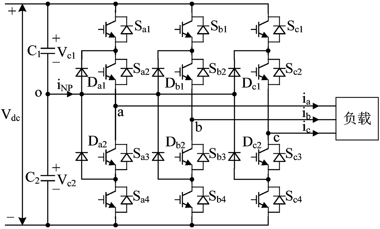
Figure 1 
Figure 2 
Figure 3
Abstract
Description
technical field
[0001] The invention relates to a three-level DC-AC power conversion device, in particular to a method for controlling the DC midpoint potential of a three-level DC-AC power conversion device. Background technique
[0002] Multilevel inverters can reduce the harmonic content of the output voltage and reduce the voltage stress of switching devices, and are widely used in high-voltage and high-power applications. Among them, the three-level neutral-point clamped inverter is the most extensively researched and applied. The prerequisite for the normal operation of the three-level neutral-point clamped inverter is that the neutral-point voltage remains balanced. The unbalanced midpoint voltage will lead to an increase in the harmonic content of the output voltage and current. If the voltage fluctuates sharply or there is a large steady-state deviation, it will lead to an increase in the voltage stress of the switch tube of the bridge arm, which may cause overvolt...
Examples
Embodiment Construction
[0033] The present invention will be further described below in conjunction with accompanying drawing.
[0034] figure 1 It is the topological structure diagram of three-phase three-level inverter. Such as figure 1 As shown, the three-phase three-level inverter includes a DC power supply V dc , DC side voltage stabilizing capacitors C1 and C2, phase A switching tube S a1 ~S a4 , A phase embedding diode D a1 and D a2 , Phase B switch S b1 ~S b4 , Phase B embedded diode D b1 and D b2 , C-phase switch S c1 ~S c4 , C-phase embedding diode D c1 and D c2 , and three-phase AC loads. Phase A switch tube S a1 ~S a4 , A phase embedding diode D a1 and D a2 Form A-phase midpoint clamping type bridge arm; B-phase switch tube S b1 ~S b4 , Phase B embedded diode D b1 and D b2 Form B-phase midpoint clamping type bridge arm; C-phase switching tube S c1 ~S c4 , C-phase embedding diode D c1 and D c2 Form C-phase midpoint embedding type bridge arm. The inverter also inc...