
Mounting structure applying pretightening force on magnetic suspension motor protection bearing
A technology for protecting bearings and motors, applied in the direction of electromechanical devices, casings/covers/supports, electrical components, etc., can solve problems such as rotor damage, and achieve the effect of reducing the possibility and increasing the size
Patent Information
- Authority / Receiving Office
- CN · China
- Current Assignee / Owner
- Publication Date
- 2018-04-24
Smart Images
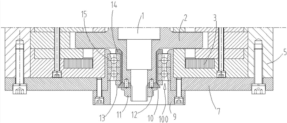
Figure 1 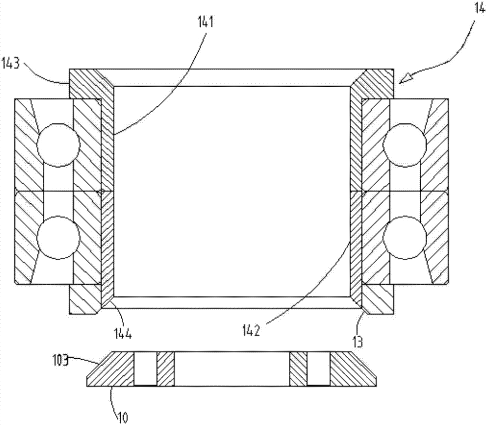
Figure 2 
Figure 3
Abstract
Description
Technical field:
[0001] The invention relates to a mounting structure for protecting a bearing of a magnetic levitation motor and adding pretightening force. Background technique:
[0002] The protective bearing of the magnetic levitation motor is an important component inside the motor. It plays the role of protecting the rotor of the motor. In the actual application process, after the rotor is unstable, it hits the protective bearing, and the rotor is seriously damaged due to the serious deformation of the protective bearing. Therefore, there are It is necessary to improve the prior art to solve the deficiencies of the prior art. Invention content:
[0003] The present invention provides an installation structure for protecting bearings of magnetic levitation motors and adding pretightening force in order to solve the above-mentioned problems in the prior art.
[0004] The technical solutions adopted in the present invention include: an installation structure for magnet...
Examples
Embodiment Construction
[0015] The present invention will be further described below in conjunction with the accompanying drawings.
[0016] Such as Figure 1 to Figure 3 , the present invention discloses an installation structure for magnetic levitation motor protection bearing plus pretightening force, including a rotor 1, a thrust disc 2, a thrust magnetic bearing 3, a machine base 5, a pressure plate 7, a gland 9, a shaft end baffle 10, Shaft end lock nut 11, stopper 13, protective bearing inner ring seat 14 and protective bearing 15, the rotor 1 is rotated and installed in the frame 5, the thrust disc 2 is sleeved on the rotor 1, and the thrust disc 2 and the rotor 1 The thrust magnetic bearing 3 is fixed in the frame 5 by screws, the inner ring seat 14 of the protective bearing is sleeved on the thrust disc 2, and the clearance fit between the inner ring seat 14 of the protective bearing and the thrust disc 2, the pressure plate 7 It is fixed on the machine base 5 by screws, and one end of the...