
Unmanned aerial vehicle supporting frame
A machine support frame and support frame technology are applied in the support frame field, which can solve the problems of inconvenient movement, insufficient stability and simple structure, and achieve the effects of convenient operation, convenient movement and reasonable design.
Patent Information
- Authority / Receiving Office
- CN · China
- Patent Type
- Applications(China)
- Current Assignee / Owner
- Publication Date
- 2018-05-04
- Estimated Expiration
- Not applicable · inactive patent
Smart Images
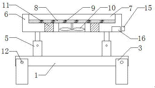
Figure 1 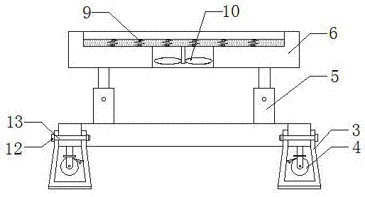
Figure 2 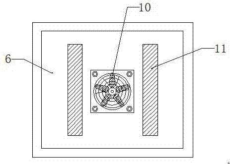
Figure 3
Abstract
Description
technical field
[0001] The invention relates to a support frame, in particular to a support frame for an unmanned aerial vehicle. Background technique
[0002] Unmanned aircraft, referred to as "unmanned aerial vehicle", or "UAV" in English, is an unmanned aircraft that is controlled by radio remote control equipment and its own program control device, or is completely or intermittently operated autonomously by an on-board computer. Drones are often better suited for missions that are too "dumb, dirty or dangerous" than manned aircraft. According to the application field, UAV can be divided into military and civilian. In terms of military use, UAVs are divided into reconnaissance aircraft and target aircraft. In terms of civilian use, drones + industry applications are the real rigid needs of drones; currently, they are used in aerial photography, agriculture, plant protection, micro selfies, express delivery, disaster relief, wildlife observation, infectious disease monit...
Examples
Embodiment Construction
[0018] The technical solutions in the embodiments of the present invention will be clearly and completely described below in conjunction with the accompanying drawings in the embodiments of the present invention. Obviously, the described embodiments are only some of the embodiments of the present invention, not all of them. Based on The embodiments of the present invention and all other embodiments obtained by persons of ordinary skill in the art without making creative efforts belong to the protection scope of the present invention.
[0019] see Figure 1-4 , the present invention provides a technical solution: a UAV support frame, including a cross bar 1, a connecting rod 2, a support leg 3, a universal self-locking wheel 4, a support frame 6 and a cooling fan 10, and the cross bar 1 is arranged side by side. There are two, two connecting rods 2 are welded in parallel between the two cross bars 1, a steel wire mesh 14 is fixed between the cross bar 1 and the connecting rod 2...