
Toy device for hitting small person
A technology of toys and figurines, applied in toys, automatic toys, entertainment, etc., can solve the problems of inability to concentrate, indurability, and inability to release the pressure of adults
Patent Information
- Authority / Receiving Office
- CN · China
- Current Assignee / Owner
- Publication Date
- 2020-04-28
Smart Images
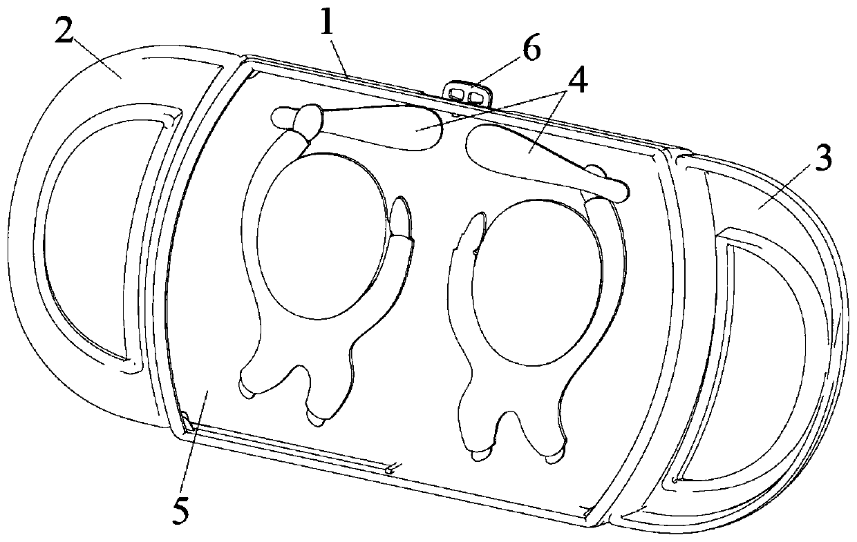
Figure 1 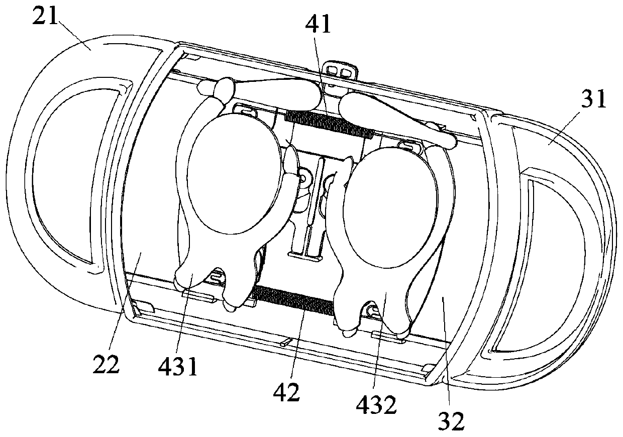
Figure 2 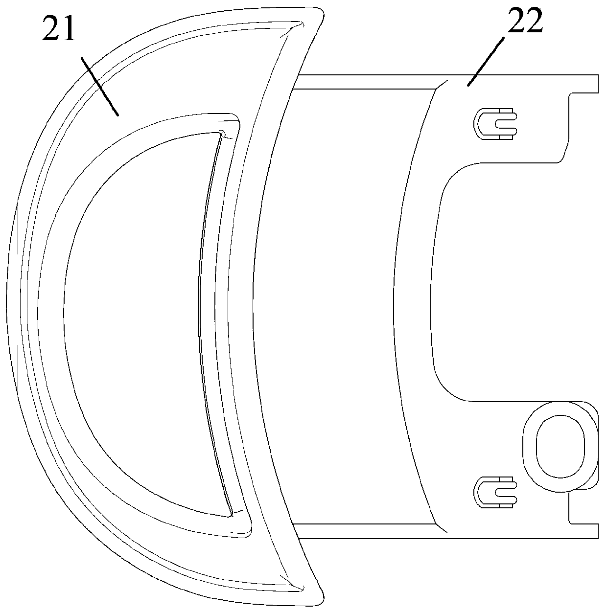
Figure 3
Abstract
Description
Technical field
[0001] The invention belongs to the technical field of toys, in particular to a toy device for playing a villain. Background technique
[0002] With the relaxation of my country's family planning policy, the proportion of children in the future will continue to increase. Toys are an important part of the children's market, so the future toy market is still a hot spot. In the age of information, children’s growth environment is now full of high-tech electronic products such as mobile phones, computers, and IPADs. In the past, children’s growth environment, such as "jumping lattice", "playing marbles", and "turning the rope", has gradually disappeared. Early exposure to a large amount of online information has created superior conditions for children’s intellectual development. However, while children benefit from the convenience of high-tech products to obtain knowledge, they are also accompanied by many foreseeable hidden dangers. Technology products are born in r...
Examples
Embodiment 1
[0054] Such as Figure 1-Figure 4 As shown, a sparring toy device provided for this embodiment includes a main casing 1, a left driving device 2, a right driving device 3, an internal sparring device 4, a transparent panel 5, and a main casing 1 The reset button 6, the toy device has a mirror-symmetrical structure;
[0055] The left driving device 2 includes a first external driving device—left handle 21 and a first internal connection part—notch plate 22 connected to the internal counter-beating device 4, and the right driving device 3 includes a second external driving device—right handle 31 and a connection At the second internal connecting portion of the internal sparring device 4—the groove plate 32; Figure 4 As shown, a groove 221 is provided on the groove plate 22; a groove 321 is provided on the groove plate 32;
[0056] The internal sparring device 4 includes an upper tension spring 41 and a lower spring 42. The groove plate 22 is provided with an upper spring sleeve con...
Embodiment 2
[0082] The difference between this embodiment and Embodiment 1 is that the driving scheme of the driving devices 2 and 3 and the personal connection modules 4312, 4322 in this embodiment is a handle gear driving scheme, that is, Picture 11 As shown, the first external driving device 21 of the left driving device 2 is a handle, the second external driving device 31 of the right driving device 3 is a handle, and the transmission part on the first internal connecting part 22 on the left is a sawtooth plate 221, The transmission part on the second internal connecting part 32 on the right is a serrated plate 321. Correspondingly, when the external driving mechanisms 21 and 31 are pulled outward, the serrated plates 221 and 321 respectively drive the serrated plate 4312-2 on the personal connection module And 4322-2 move, thereby driving the first person connecting module 4312 and the second person connecting module 4322 to rotate.
Embodiment 3
[0084] The difference between this embodiment and the embodiment 1-2 is that the driving scheme of the driving devices 2 and 3 and the personal connection modules 4312, 4322 in this embodiment is the button groove cam rotation plate driving scheme, ie Picture 12 As shown, the first external drive device 21 of the left drive device 2 is a button mechanism, including a button protrusion 211 protruding from the outside of the main housing, as a button connection portion of the transmission portion 221 of the first internal connection portion 22, the button connection The part is a serrated plate 212 with a groove 2121. The groove 2121 cooperates with the fixed protrusion 141 on the main housing to move the serrated plate 212 up and down. The serrated plate 212 is clamped to the spring 213, and the other end of the spring 213 is clamped. At the bottom of the main housing 1;
[0085] The second external drive device 3 of the left drive device 3 is a button mechanism, including a butto...