
Carding machine slivering mechanism
A carding and sliver technology, applied in the field of carding processing, can solve the problems of sliver mold, high moisture regain of sliver, failure of wire rod, etc.
Patent Information
- Authority / Receiving Office
- CN · China
- Patent Type
- Applications(China)
- Current Assignee / Owner
- Publication Date
- 2020-12-04
Smart Images
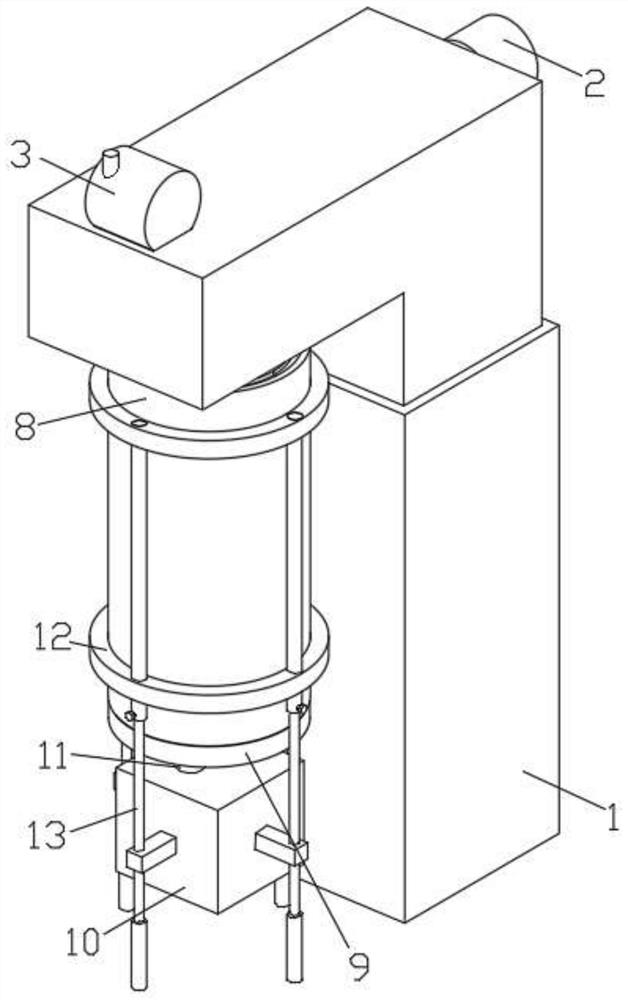
Figure 1 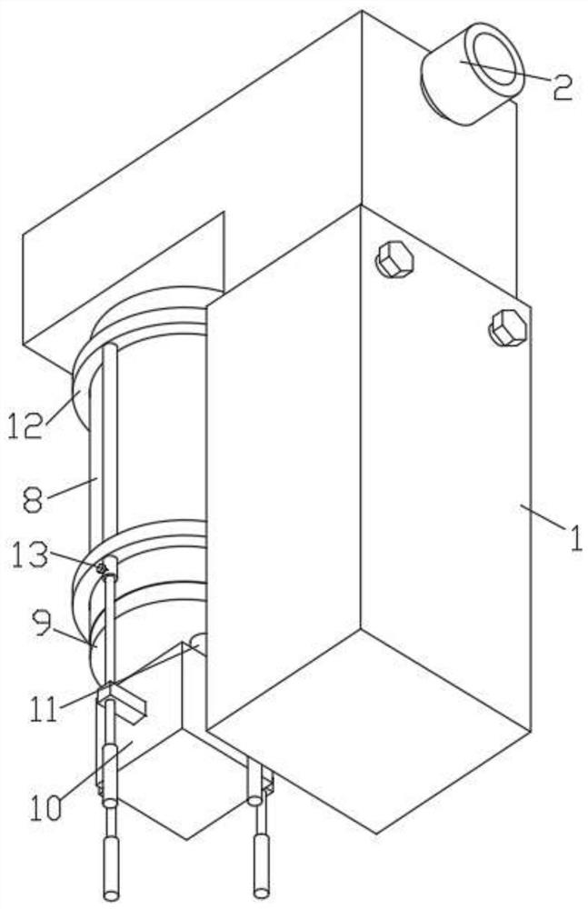
Figure 2 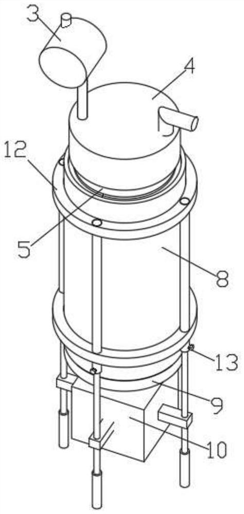
Figure 3
Abstract
Description
technical field
[0001] The invention relates to the technical field of carding processing, in particular to a sliver forming mechanism of a carding machine. Background technique
[0002] With the widespread use of cotton products, more and more factories have begun to use carding machinery for cotton processing and processing. Therefore, a carding machine sliver mechanism is needed for cotton processing plants.
[0003] At present, there are many types of carding machine sliver mechanisms on the market. Most of the existing card sliver mechanisms use independent metal cylinders for sliver storage, but the airtight treatment of such devices is not enough, and often such devices will Affected by the humidity of the working environment, the moisture regain of the sliver is too high, resulting in mold on the sliver. At the same time, during the process of reeling the sliver, the independent metal cylinder cannot provide a limit card for the reel of the sliver. Grooves often ca...
Examples
Embodiment Construction
[0043] The following will clearly and completely describe the technical solutions in the embodiments of the present invention with reference to the accompanying drawings in the embodiments of the present invention. Obviously, the described embodiments are only some, not all, embodiments of the present invention.
[0044] see Figure 1 to Figure 5, the present invention provides a technical solution: a carding machine sliver mechanism, including a shell 1, the outer shell 1 is provided with a circular hole, and the circular hole outside the shell 1 is fixedly connected with a material guide pipe 2, The top of the casing 1 is fixedly connected with an exhaust fan 3, and the bottom end of the exhaust duct of the exhaust fan 3 is fixedly connected with a top cover 4, and the bottom of the top cover 4 is movably connected with an inner tank 5, and the inner cavity of the inner tank 5 is provided with a cylindrical hole , and the inner cavity of the liner 5 is movably connected with...