
Data synchronization method of electroencephalogram device and electroencephalogram device
An EEG device and data synchronization technology, which is applied in the field of bioinformatics, can solve the problems of slow transmission speed, difficulty in synchronous acquisition of multiple stimulation systems, complicated transmission process, etc., and achieve the effect of avoiding delay
Patent Information
- Authority / Receiving Office
- CN · China
- Patent Type
- Applications(China)
- Current Assignee / Owner
- Publication Date
- 2021-07-23
Smart Images
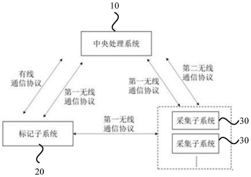
Figure 1 
Figure 2 
Figure 3
Abstract
Description
technical field
[0001] Embodiments of the present invention relate to the field of biological information technology, and in particular, to a data synchronization method for an EEG device and the EEG device. Background technique
[0002] Event-related evoked potential (ERP) is an electroencephalogram (EEG) induced by a specific stimulus, which can reflect the neurophysiological changes in the cognitive process of the brain under the stimulus. In the process of EEG signal acquisition, events and data often have a strict time-locked relationship, such as event-related evoked potentials (ERPs) and phase-related steady-state visual evoked potentials. Therefore, while recording the EEG data, it is necessary to accurately record the time when the event occurs, and the time error between the event and the data is required to be within ±1ms.
[0003] Existing synchronization methods mainly include two types: one is digital wired synchronization, specifically: the event generator ca...
Examples
Embodiment Construction
[0050] The present invention will be further described in detail below in conjunction with the accompanying drawings and embodiments. It should be understood that the specific embodiments described here are only used to explain the present invention, but not to limit the present invention. In addition, it should be noted that, for the convenience of description, only some structures related to the present invention are shown in the drawings but not all structures.
[0051] figure 1 is a schematic structural diagram of an EEG device provided by an embodiment of the present invention, such as figure 1 As shown, the EEG device 100 provided by the embodiment of the present invention includes a central processing system 10, a marking subsystem 20 and at least one acquisition subsystem 30, wherein, figure 1 The description is made by taking the EEG device 100 including two acquisition subsystems 30 as an example. The central processing system 10 is configured to send instructions...