
Device and method for generating microbubbles and hydrates in situ by using visual kettle
A technology of microbubbles and hydrates, applied in measuring devices, chemical method analysis, instruments, etc., can solve problems such as slow formation rate, high formation conditions, and environmental damage
Patent Information
- Authority / Receiving Office
- CN · China
- Patent Type
- Applications(China)
- Current Assignee / Owner
- Publication Date
- 2021-09-07
Smart Images
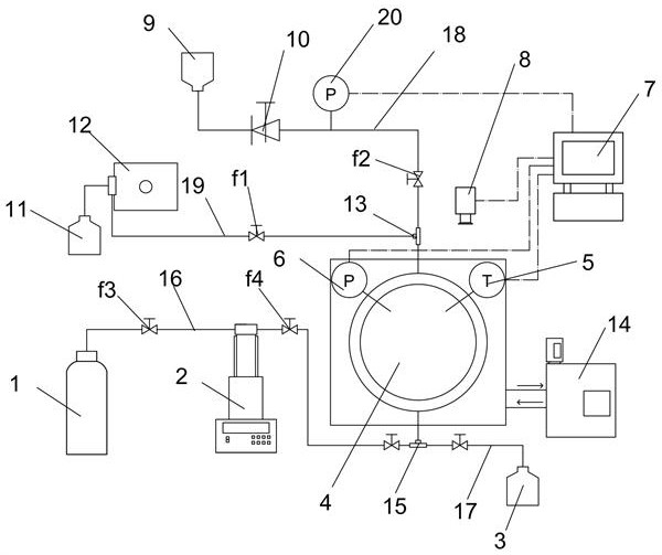
Figure 1 
Figure 2 
Figure 3
Abstract
Description
technical field
[0001] The invention belongs to the field of hydrate application, and relates to an experimental device and method for generating microbubbles and hydrate in situ by using a visible kettle. Background technique
[0002] Due to their small size, microbubbles (bubbles with a diameter of 10-100μm) can show many characteristics different from ordinary bubbles, such as high mass transfer efficiency, long existence time, self-pressurization and dissolution, etc. According to the principle of buoyancy, the larger the volume of the bubble, the greater the buoyancy it receives, and the faster the rising speed. However, due to its small size, the buoyancy of the microbubble in the solution is much smaller than that of ordinary bubbles in water. Therefore, Microbubbles float slowly and stay in the water longer. According to the surface tension theory of the gas-liquid interface, the smaller the diameter of the bubble, the more obvious the influence of its surface tensi...
Examples
Embodiment 2
[0057] Example 2 Observation of microbubbles using a porous plate visual kettle
[0058] a. Initial preparation and injection stage
[0059] a1, turn on the cooling circulation pump 14 to reduce the temperature in the kettle to the experimental temperature of 20°C and the data acquisition system 7; configure the pure water of the experimental solution to the solution bottle, and saturate the injection pump 12 with the experimental solution;
[0060] a2. Open the needle valve v1 at the liquid inlet end, and turn on the liquid injection pump 12 to inject liquid at a fixed flow rate of 9.9 mL / min to the amount of solution required for the experiment;
[0061] a3. Close the needle valve v1 at the liquid inlet end, set the value of the back pressure valve 10 to 0MPa, open the needle valve v2 at the exhaust end, and draw a vacuum through the back pressure valve 10, and set the value of the back pressure valve 10 to the required value for the experiment after exhausting Pressure val...
Embodiment 3
[0071] Example 3 Data processing of the microbubble pictures collected by the camera
[0072] a. Add image scales in batches
[0073] a1. Open the macro recorder (Marcos) of ImageJ software;
[0074] a2, open the picture with scale, use the set scale function to add scale; close the macro recorder, get the macro file with scale added;
[0075] a3. Use the batch processing function (process-batch) to import the image sequence to be processed in batches; run the macro file to obtain the image sequence with scale;
[0076] b. Automatically count the bubble area
[0077] b1. Use process-sharpen or adjust-contrast to adjust the picture to make the picture clearer;
[0078] b2. Adjust the image threshold (adjust-threshold) to binarize the image;
[0079] b3. Use process-binary-fill holes to fill the gaps in the bubbles; use process-binary-watershed to automatically segment the bubble boundaries;
[0080] b4. Automatically count the bubble area through image analysis (analyze-pa...
Embodiment 4
[0086] Example 4 Formation of Hydrate in Visible Kettle Using Porous Plate
[0087] a. Initial preparation and injection stage
[0088] a1, turn on the cooling circulation pump 14 to reduce the temperature in the kettle to the experimental temperature of 1°C and the data acquisition system 7; configure the experimental solution 500ppm SDS solution to the solution bottle, and saturate the injection pump 12 with the experimental solution;
[0089] a2. Open the needle valve v1 at the liquid inlet end, and turn on the liquid injection pump 12 to inject liquid at a fixed flow rate of 9.9 mL / min to the amount of solution required for the experiment;
[0090] a3. Close the needle valve v1 at the liquid inlet end, set the value of the back pressure valve 10 to 0MPa, open the needle valve v2 at the exhaust end, and draw a vacuum through the back pressure valve 10, and set the value of the back pressure valve 10 to the required value for the experiment after exhausting The pressure val...