
Separating and filtering device for extracting plant flower perfume
A technology for separation, filtration and extraction devices, which is applied in the direction of filtration and separation, separation methods, fixed filter elements, etc. It can solve the problems of waste, inconvenient disassembly, and plant debris staying on the inner wall of the container, so as to reduce waste and increase The effect of breaking range
Patent Information
- Authority / Receiving Office
- CN · China
- Patent Type
- Applications(China)
- Current Assignee / Owner
- Publication Date
- 2022-03-29
Smart Images
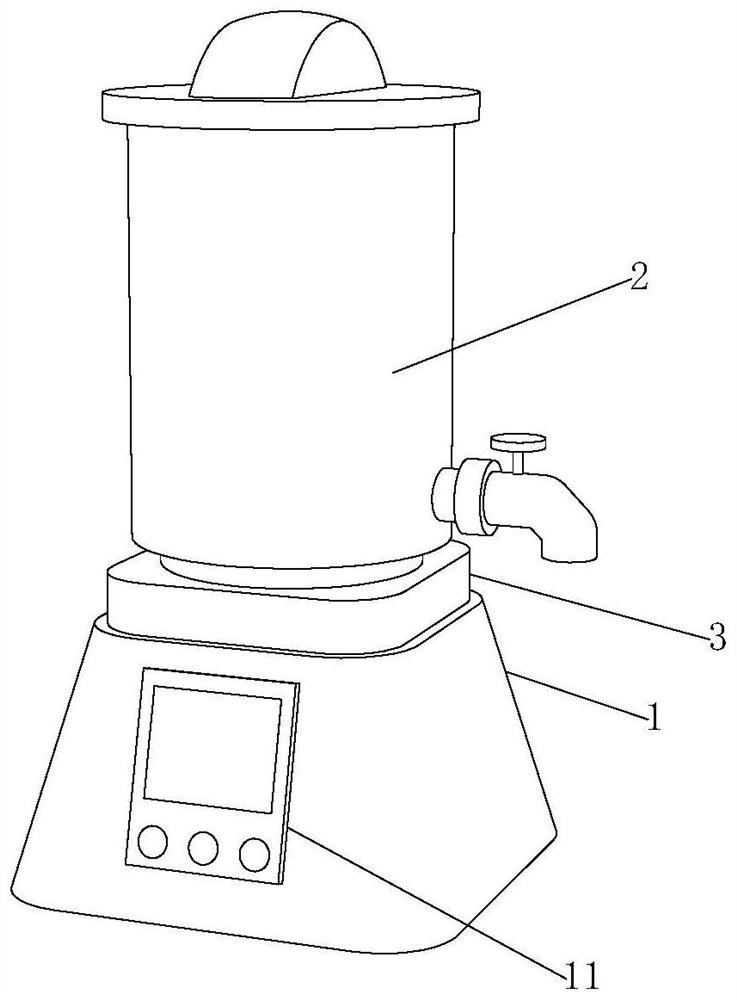
Figure 1 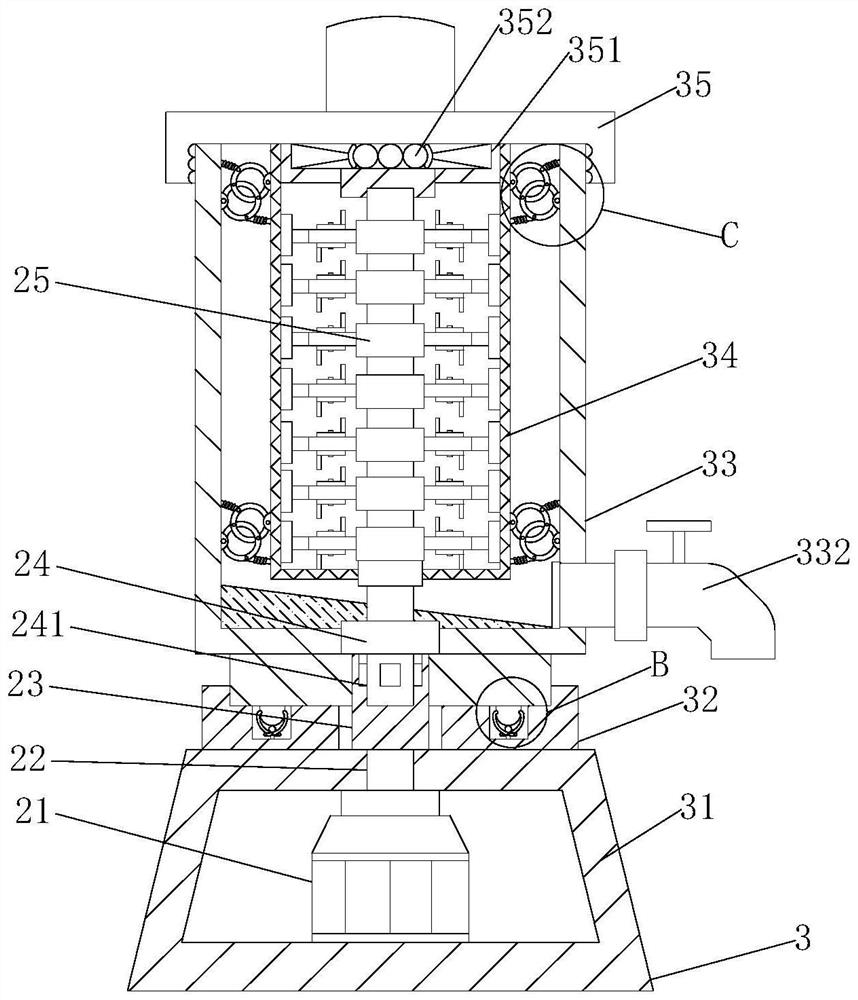
Figure 2 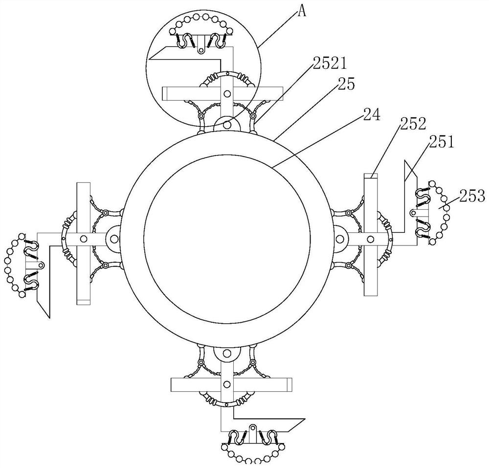
Figure 3
Abstract
Description
technical field
[0001] The invention relates to the technical field of plant flower fragrance extraction, in particular to a separation and filtration device for plant flower fragrance extraction. Background technique
[0002] The extraction of plant flower spices has only been developed in recent decades, and it is an emerging industry between the pharmaceutical, fine chemical, and agricultural industries. The extraction of plant flower spices is based on plants as raw materials. According to the needs of the final product of extraction, through the process of physical and chemical extraction and separation, one or more aroma components in plants are directional obtained and concentrated. The extraction of plant flower spices requires A separation filter is used.
[0003] There are following problems at prior art:
[0004] 1. In the prior art, plant extraction needs to be broken first and then transferred to the filter for filtration. The operation is complicated and the ...
Examples
Embodiment 1
[0031] Such as Figure 1-6 As shown, the present invention provides a separation and filtration device for extracting plant flower spices, comprising an extraction separation and filtration device main body 1, the outer surface of the extraction separation and filtration device main body 1 is provided with a control screen 11, and the inside of the control screen 11 is provided with The wall-breaking extraction device 2 is provided with a separation and filtering device 3 outside the wall-breaking extraction device 2. The wall-breaking extraction device 2 includes a motor 21, a rotating shaft 22, a clamping seat 23, a wall-breaking rotating shaft 24 and a breaking-wall grinding and extracting mechanism 25, The output end of the motor 21 is fixedly connected with the lower end of the rotating shaft 22, and the separation filter device 3 includes a base 31, a mounting seat 32, an extraction liquid collection tank 33, a residue filter screen 34, a sealing cover 35 and a connecting...
Embodiment 2
[0034] Such as Figure 1-6As shown, on the basis of embodiment 1, the present invention provides a kind of technical scheme: the outer surface of broken wall grinding extraction mechanism 25 is fixedly installed with L-shaped blade 251, and the surface of L-shaped blade 251 is movably installed with Z-shaped blade 252, The inner side of the Z-shaped blade 252 is fixed with an elastic connector 2521, one end of the elastic connector 2521 is fixedly connected with the surface of the L-shaped blade 251, and the middle end of the elastic connector 2521 is fixedly connected with the outer surface of the broken wall grinding extraction mechanism 25, Z-shaped The outer side of blade 252 is fixedly equipped with movable rod 2522, and the center of movable rod 2522 is movably connected with the surface of L-shaped blade 251, and the outer side of L-shaped blade 251 is movably equipped with grinder 253, and moves between grinder 253 and L-shaped blade 251 A connecting rod 2531 is instal...
Embodiment 3
[0037] like Figure 1-6 As shown, on the basis of Embodiment 1, the present invention provides a technical solution: the lower surface of the extraction liquid collection tank 33 is movably connected with the upper surface of the mounting seat 32, and the lower surface of the extraction liquid collection tank 33 is fixedly installed with a limit post 331, the upper surface of the mounting seat 32 is provided with a jack that is compatible with the limit column 331, the upper surface of the mounting seat 32 is provided with a limit snap ring 321, and the center of the limit snap ring 321 is equipped with an extrusion column 322 , the lower end of the extrusion column 322 is fixedly connected to the inner wall of the mounting seat 32, the upper end of the limit snap ring 321 and the extrusion column 322 are in contact with the outer surface of the limit post 331, and both sides of the limit snap ring 321 are fixedly installed with The reset rod 323 , the two ends of the reset ro...