
Overlapped double rotor generator and its speed changing and frequency changing exciting system
A frequency conversion excitation and generator technology, which is applied to control generators and control generators and engines through magnetic field changes. And other issues
Patent Information
- Authority / Receiving Office
- CN · China
- Patent Type
- Applications(China)
- Current Assignee / Owner
- Publication Date
- 2007-06-27
- Estimated Expiration
- Not applicable · inactive patent
Smart Images
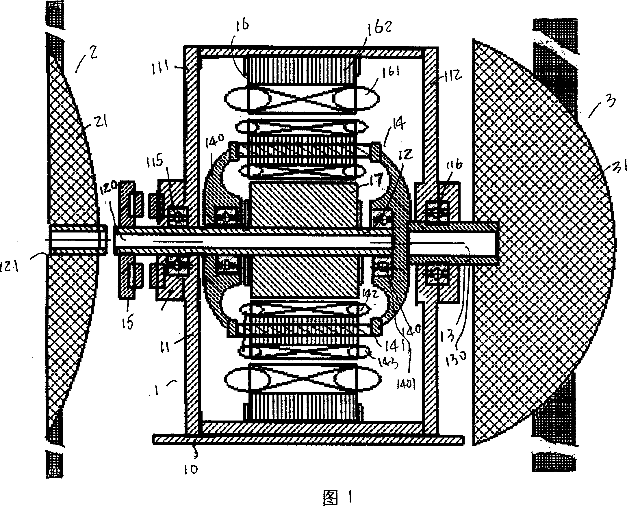
Figure 1 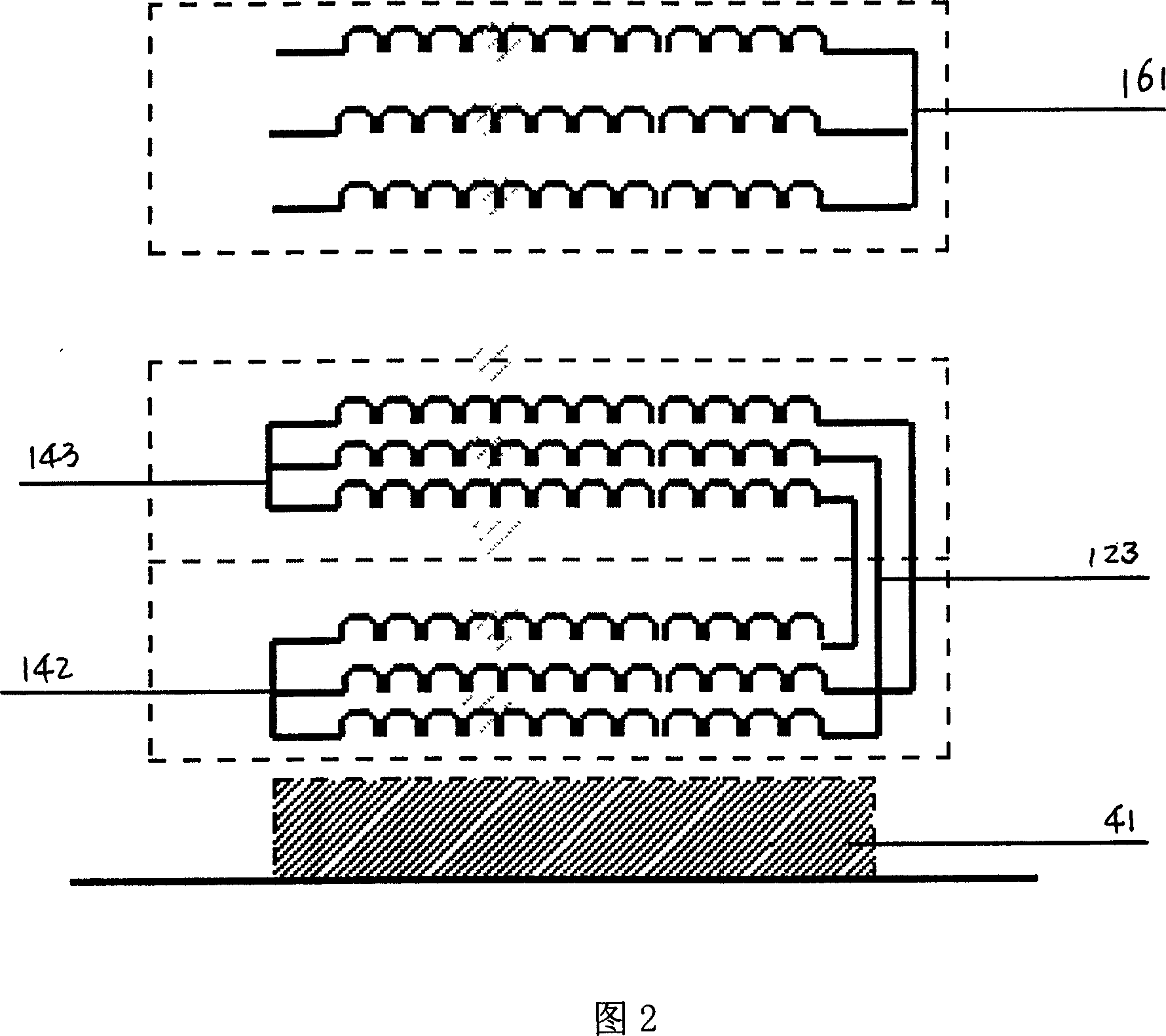
Figure 2 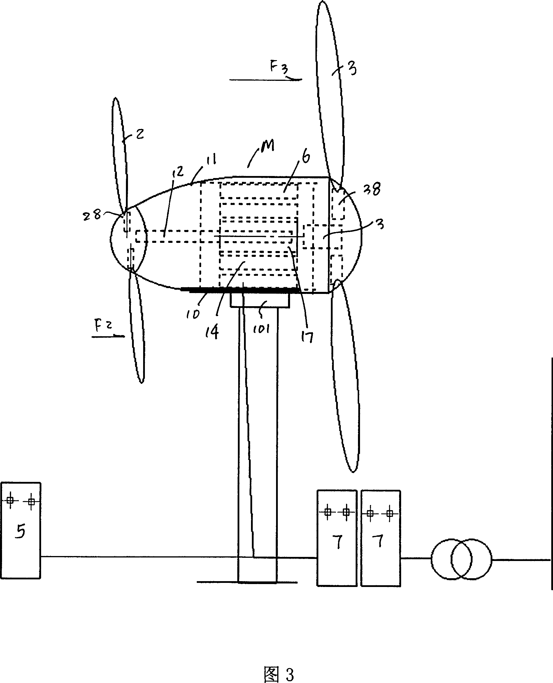
Figure 3
Abstract
Description
technical field
[0001] The invention relates to a wind power generator, in particular to a variable-speed variable-frequency generator with a telescoping double-rotor excitation structure and an excitation control system thereof. Background technique
[0002] Known technology such as Chinese patent CN200510022771.1 discloses that the present invention discloses a variable speed and constant frequency method for wind power generation. The power Pw is input to the input shaft of the differential permanent magnet motor, and the differential mechanism of the differential permanent magnet motor performs power division or confluence to generate power flow Pg, which enters the stator winding of the differential permanent magnet motor and realizes constant speed and constant frequency power generation to the power grid through the feeder . Compared with the traditional method of variable speed and constant frequency, the present invention can significantly improve the power generat...
Examples
Embodiment Construction
[0036] The specific implementation, structure, features and effects provided by the present invention will be described in detail below in conjunction with the accompanying drawings and preferred embodiments.
[0037] As shown in Figures 1-4, a telescopic double-rotor variable-speed variable-frequency generator includes a generator body 1 fixed on a base 10, and a generator stator 16 fixed in a casing 11 of the generator body, wherein,
[0038] The permanent magnet inner rotor 17 is driven by the auxiliary drive 12 and rotates relative to the stator 16, and is installed in the main casing of the generator;
[0039] The ring rotor 14 is driven by the main transmission shaft 13, the ring rotor is a structural device that surrounds and can rotate around the permanent magnet inner rotor, and the ring rotor 14 is configured to rotate relative to the stator 16; the ring rotor 14 is supported by the ring rotor The unit 140 surrounds the aforementioned permanent magnet inner rotor 17 ...