
Straddle-type vehicle
A straddle-type, vehicle technology, applied in the field of straddle-type vehicles, can solve problems such as the inability of straddle-type vehicles to drive
Patent Information
- Authority / Receiving Office
- CN · China
- Patent Type
- Applications(China)
- Current Assignee / Owner
- Publication Date
- 2007-07-04
- Estimated Expiration
- Not applicable · inactive patent
Smart Images
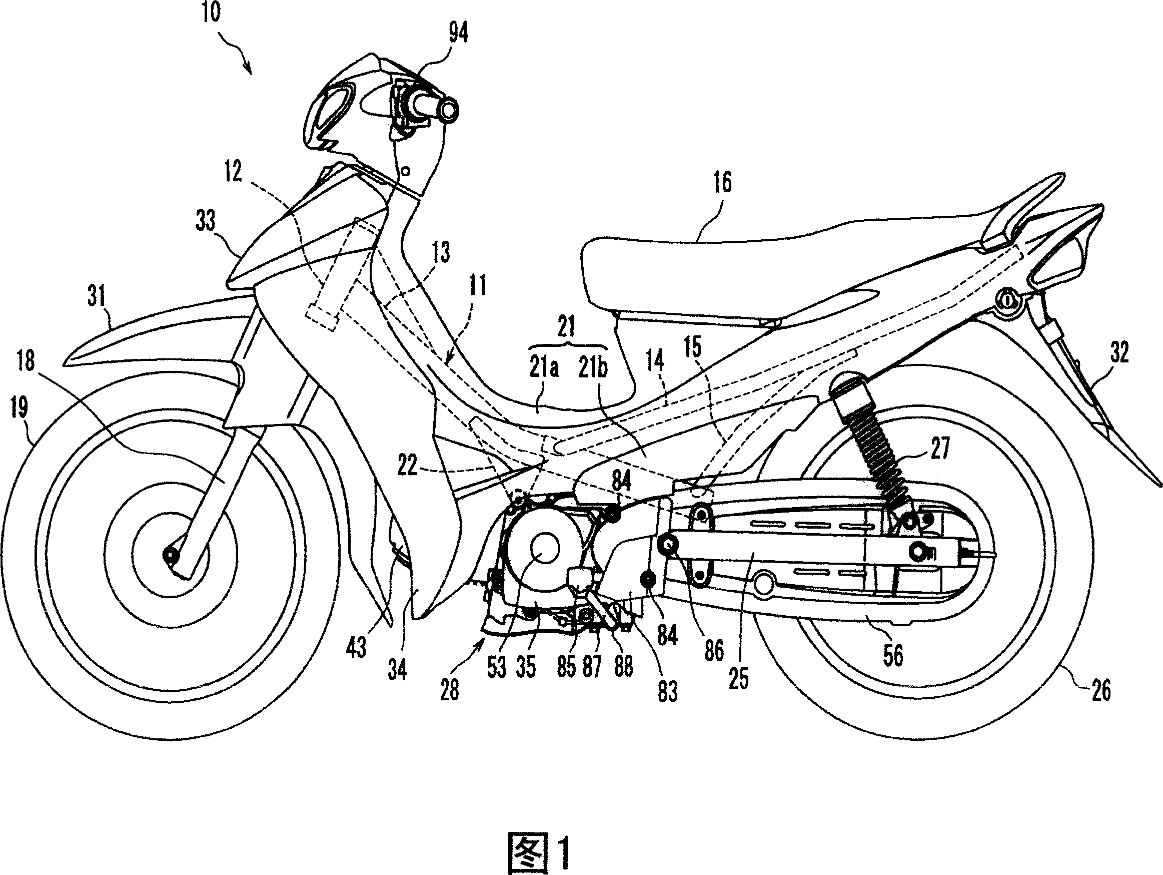
Figure 1 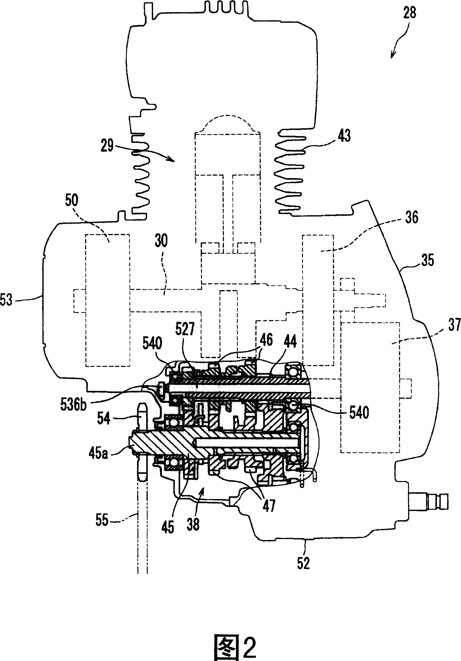
Figure 2 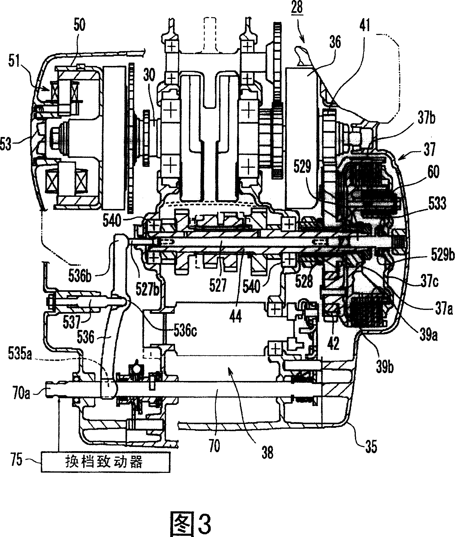
Figure 3
Abstract
Description
technical field
[0001] The present invention relates to a straddle type vehicle equipped with an automatic transmission. Background technique
[0002] Known straddle vehicles include straddle vehicles equipped with a transmission having multiple gears and clutches that are engaged or disengaged when changing gears. Straddle-riding vehicles of this type also include vehicles having a clutch actuator for engaging or disengaging a clutch and a shift actuator for actuating a shift operation of the transmission such that Engagement and release of the clutch and shifting can be automatically performed (refer to Patent Document 1).
[0003] The straddle type vehicle is constructed such that the clutch actuator and the shift actuator are controlled to be synchronized with each other. Therefore, the clutch on-off operation and the shift operation of the transmission are performed at appropriate timings. Therefore, if one of the actuators of a straddle vehicle equipped with a clutc...
Examples
no. 1 example
[0047] Referring to FIG. 1 , the straddle-type vehicle according to the present invention is a motorcycle 10 . The motorcycle 10 includes a body frame 11 constituting a frame and a rider's seat 16 . The motorcycle 10 is of the so-called moped type. "Motorized" here refers to the type of vehicle in terms of shape only, without limiting the maximum speed, piston stroke, and size of the vehicle. The straddle type vehicle according to the present invention is not limited to a motorized pedal type, but may be other types of motorcycles with a fuel tank in front of the seat, or other types of straddle type vehicles such as three-wheeled motorcycles or off-road vehicles (ATVs). style vehicles.
[0048] In the following description, front, rear, left, and right refer to directions viewed by a rider sitting on the saddle 16 . The body frame 11 includes: a steering head pipe 12; a main frame 13 extending obliquely downward from the steering head pipe 12; a pair of left and right seat...
no. 2 example
[0116] Referring to Fig. 12 and Fig. 13, the second embodiment is a modification of the first embodiment, in which the rod 63 of the connecting device 61 is modified.
[0117] In the second embodiment, the rod 63 is composed of a plurality of rod members detachably connected together. Here the rod 63 is composed of a first rod member 91 and a second rod member 92 .
[0118]14(a) and 14(b), the second rod member 92 has a substantially U-shaped clamp 92a at the top opening upward. The clamp 92a has two upper and lower circular holes 92b and two upper and lower nuts 92c corresponding to the circular holes 92b. The first lever member 91 has an insertion portion 91a at a lower portion to be inserted into a jig 92a. The insertion portion 91a has two vertical long holes 91b.
[0119] As shown in FIG. 13 , the first rod member 91 and the second rod member 92 are fastened by bolts 93 passing through the round hole 92b, the elongated hole 91b, and the nut 92c. Since the insertion po...