
Power conversion device
A power conversion device and power supply technology, applied in the direction of output power conversion device, AC motor deceleration device, electric motor/converter plug, etc., can solve the problem of consuming regenerative energy of the motor
Patent Information
- Authority / Receiving Office
- CN · China
- Patent Type
- Applications(China)
- Current Assignee / Owner
- Publication Date
- 2016-08-10
- Estimated Expiration
- Not applicable · inactive patent
Smart Images
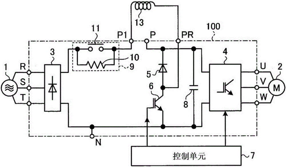
Figure 1 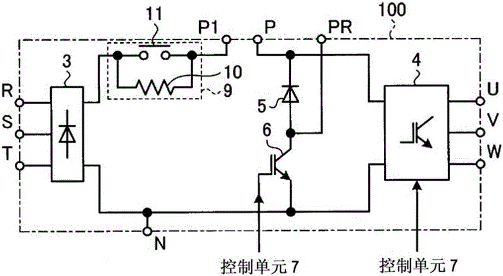
Figure 2 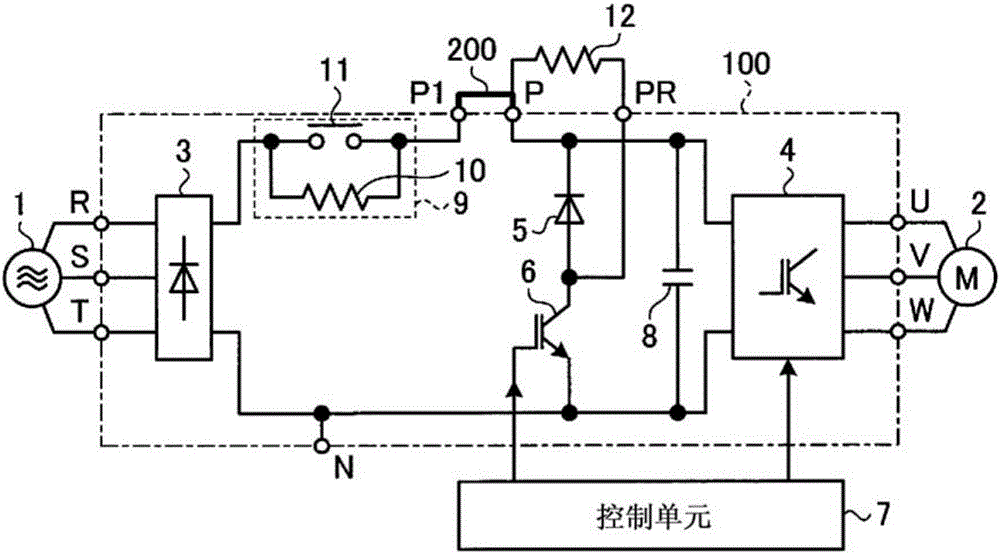
Figure 3
Abstract
Description
technical field
[0001] The invention relates to a power conversion device. Background technique
[0002] A power conversion device for driving a motor that rectifies AC supplied from an AC power source and converts the rectified DC into AC to drive a motor generally has a structure including a brake transistor for passing current The regenerative energy when the motor decelerates is consumed by flowing through an external resistor. On the other hand, a structure that operates stably even when the voltage of the AC power source fluctuates or a voltage drop occurs is sought, and a structure that can improve the torque and output of the motor can be realized.
[0003] Currently, an electric power steering apparatus that drives an electric power steering motor has disclosed a configuration capable of switching between a boost operation and a regenerative operation (for example, Patent Document 1).
[0004] Patent Document 1: Japanese Patent Laid-Open No. 2004-166441 Contents...
Examples
Embodiment approach 1
[0026] figure 1 It is a figure which shows an example of a structure of the power conversion apparatus concerning Embodiment 1. in addition, figure 2 is a diagram showing an example of the configuration of the main circuit, where the main circuit constitutes figure 1 The power conversion device shown. Such as figure 2 As shown, the main circuit 100 has: a rectification circuit 3, which is composed of a plurality of rectification elements connected in a full bridge, and is supplied with AC power through terminals R, S, and T; an inverter 4, which is composed of a plurality of switching elements. Bridge connection to drive the load; diode 5, the cathode of which is connected to the positive side power supply path toward the inverter 4; and a switching element 6, which is connected to the anode of the diode 5 and the rectifier circuit 3 and the inverter 4 between the negative side power supply paths. The switching element 6 can be constituted by, for example, a power trans...
Embodiment approach 2
[0049] Figure 7 It is a diagram showing a configuration example of a power conversion device according to Embodiment 2. in addition, Figure 8 is a diagram showing an example of the configuration of the main circuit, where the main circuit constitutes Figure 7 The power conversion device shown. in addition, Figure 9 is directed at Figure 8 The main circuit of the shown configuration is a diagram showing a configuration example in the case of performing a regenerative power consumption operation. exist Figure 7 , 8 In the example shown in , 9, the following example is shown, that is, in the main circuit 100b, the anode of the diode 5 is connected to the negative side power supply path, and the switching element 6 is connected to the cathode of the diode 5 and the rectifier circuit 3 and the inverter. Between the positive side power supply paths between the devices 4.
[0050] In addition, the main circuit 100b has an N terminal (first terminal) provided on the nega...
Embodiment approach 3
[0061] Figure 13 It is a diagram showing a configuration example of a power conversion device according to Embodiment 3. exist Figure 13 In the example shown, instead of the diode 5 and the switching element 6 described in Embodiments 1 and 2, the main circuit 100d has the following components: a first diode 5a and a second diode 5b, the cathodes of which are directed in the opposite direction. The positive side power supply path of the inverter 4 is connected; the first switching element 6a is connected between the anode of the first diode 5a and the negative side power supply path toward the inverter 4; and the second switching element 6b is connected between the negative-side power supply path to the inverter 4 and the anode of the second diode 5b.
[0062] In addition, in Figure 13 In the example shown, the PR1 terminal (third terminal) is provided at the connection point between the first diode 5a and the first switching element 6a, and the PR2 terminal (third termi...