
Self-propelled cleaner
A vacuum cleaner and self-propelled technology, which is applied in the installation of vacuum cleaners, household appliances, electrical equipment, etc., can solve the problems that the side brush cannot be used to sweep out and remove dust, the side brush cannot reach, etc., so that the structure will not be complicated, The effect that the number of parts does not increase
Patent Information
- Authority / Receiving Office
- CN · China
- Patent Type
- Applications(China)
- Current Assignee / Owner
- Publication Date
- 2017-05-31
Smart Images
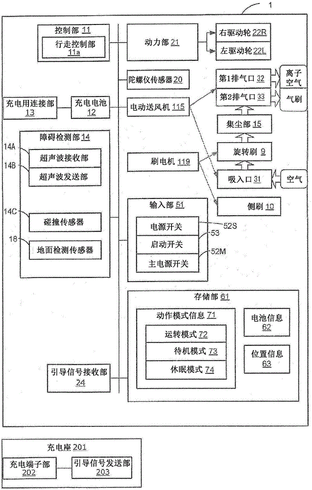
Figure 1 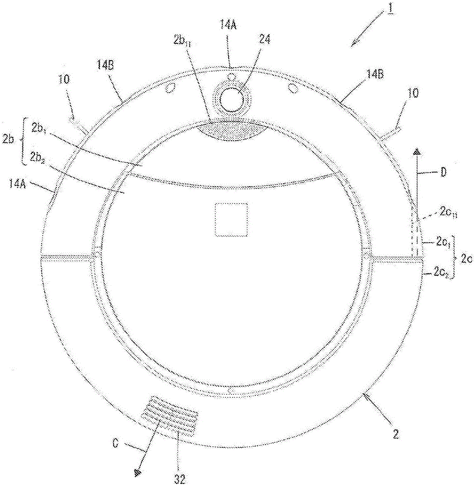
Figure 2 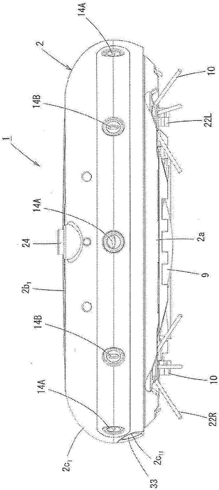
Figure 3
Abstract
Description
technical field
[0001] The present invention relates to a self-propelled vacuum cleaner. Background technique
[0002] As a conventional self-propelled vacuum cleaner, the following self-propelled vacuum cleaner (Prior Art 1) is disclosed in Patent Document 1, which is provided with: side brushes provided on the left and right sides of the bottom front of the box; Between a pair of left and right side brushes at the bottom of the box; and a suction device, which is arranged in the box, and sucks the dust on the ground together with the air from the suction port.
[0003] In addition, Patent Document 1 discloses a self-propelled vacuum cleaner (Prior Art 2) provided with: nozzle holes provided on the left and right sides in front of the bottom of the box; and suction ports provided in the bottom of the box. Between a pair of nozzle holes on the left and right; a suction device, which is set in the box, sucks the dust on the ground together with the air from the suction port;...
Examples
Embodiment approach 1
[0035] figure 1 It is a block diagram showing the electrical configuration of the self-propelled (vacuum) cleaner according to Embodiment 1 of the present invention. in addition, figure 2 It is a plan view of the self-propelled (vacuum) cleaner according to Embodiment 1 of the present invention, image 3 yes figure 1 The front view of the self-propelled vacuum cleaner shown, Figure 4 yes figure 1 A side view of the self-propelled vacuum cleaner shown, Figure 5 yes figure 1 The rear view of the self-propelled vacuum cleaner shown, Figure 6 yes figure 1 Bottom view of the self-propelled vacuum cleaner shown. in addition, Figure 7 yes figure 1 A top sectional view of the self-propelled vacuum cleaner shown, Figure 8 yes figure 1 Another top sectional view of the self-propelled vacuum cleaner shown. in addition, Figure 9 yes figure 1 A side sectional view of the self-propelled vacuum cleaner shown, Figure 10 yes figure 1 Side sectional view of the...
Embodiment approach 2
[0097] In Embodiment 1, the rear half 2c of the side plate 2c of the box 2 is illustrated as an example. 2 and the ribs 2d provided on the inner structural wall 2d 1 、2d 2 In the case of forming the second exhaust air passage 35, it is also possible to install various components on the internal structure wall 2d and the rear half 2c of the side plate 2c. 2 A gap is formed between them to form a second exhaust air path.
Embodiment approach 3
[0099] In the case of Embodiment 1, since the output of the electric blower 115 is constant, the airflow F from the second exhaust port 33 1 The air volume is also fixed.
[0100] Therefore, in Embodiment 3, it may be that when Figure 11 (A) and Figure 11 As shown in (B), in the self-propelled vacuum cleaner 1, when the front ultrasonic receiver 14A detects the front wall W2, the output of the electric blower 115 is increased (for example, 1.3 to 1.5 times) than the normal level, and this is accompanied by this. , so that the air flow F blown out from the second exhaust port 33 2 The air volume increases. Thereby, the cleaning force with respect to the corner part K where the dust Q tends to accumulate can be improved. Moreover, when the front ultrasonic wave receiving part 14A no longer detects a wall surface, the output of the electric blower 115 will return to a normal level.