
Support for a crane
a technology for supporting a crane and a crane body, which is applied in the direction of braking devices for hoisting equipment, base supporting structures, load-engaging elements, etc., can solve the problems of crane loss of stability, overall load bearing capacity, and inability to simultaneously support all the tilt edges of the crane, and achieves the effect of light and as inexpensiv
Patent Information
- Authority / Receiving Office
- US · United States
- Patent Type
- Patents(United States)
- Current Assignee / Owner
- Publication Date
- 2020-09-22
Smart Images
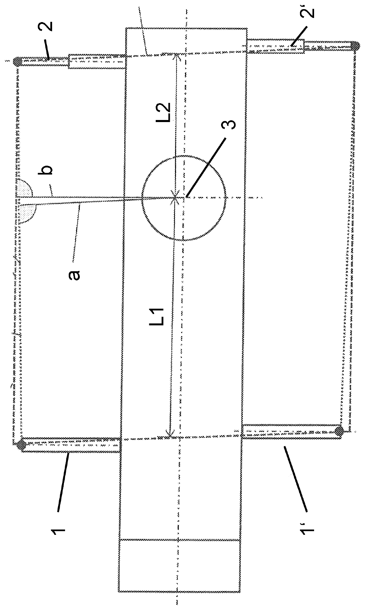
Figure 1
Abstract
Description
CROSS REFERENCE TO RELATED APPLICATION
[0001] This application claims priority to German Patent Application No. 10 2017 001 128.1, entitled “Support for a Crane,” filed Feb. 7, 2017, the entire contents of which is hereby incorporated by reference in its entirety for all purposes.TECHNICAL FIELD
[0002] The present disclosure relates to a support for a crane, in particular for a mobile crane, having at least two first support beams and two second support beams that are each arranged pairwise at mutually oppositely disposed sides of the vehicle frame.BACKGROUND AND SUMMARY
[0003] When configuring cranes or supports for cranes, an optimized ratio of tilt edges to one another inter alia plays an exceptional role. The spacing of the contact point of a slewing platform on an undercarriage of a corresponding crane from the individual tilt edges of the crane in a working position and in this respect from correspondingly extended or supported support beams is inter alia fixed in this process. The ...
Examples
Embodiment Construction
[0020]The two first mutually oppositely disposed support beams 1, 1′ here have a smaller maximum deployment range than the two second mutually oppositely disposed support beams 2, 2′. The maximum deployment range can here be defined as the maximum horizontal extent of the support beams 1, 1′, 2, 2′ perpendicular to the longitudinal axis of the support and away from the support. This extent is at a maximum when the support beams 1, 1′, 2, 2′ have been telescoped or pivoted outwardly. The longitudinal axis of the support is recognizable as the longest, transversely extending chain-dotted line.
[0021]The dashed and dotted lines show the extent of a parallelogram-shaped support base from the prior art (dashed) and of a trapezoidal or at least approximately trapezoidal support base in accordance with the present disclosure (dotted).
[0022]Lateral tilt edges of the support bases are shown at the top and bottom in FIG. 1 and front or rear tilt edges of the support bases that are associated w...