
Centrifugal clutch and cover mount assembly therefor
a technology of centrifugal force and cover mount, which is applied in the direction of mechanical actuators, clutches, and clutches, etc., can solve the problems of insufficient centrifugal force generated to clamp the clutch plates together without substantial slipping or withou
Patent Information
- Authority / Receiving Office
- US · United States
- Patent Type
- Applications(United States)
- Current Assignee / Owner
- Publication Date
- 2004-12-02
- Estimated Expiration
- Not applicable · inactive patent
Smart Images
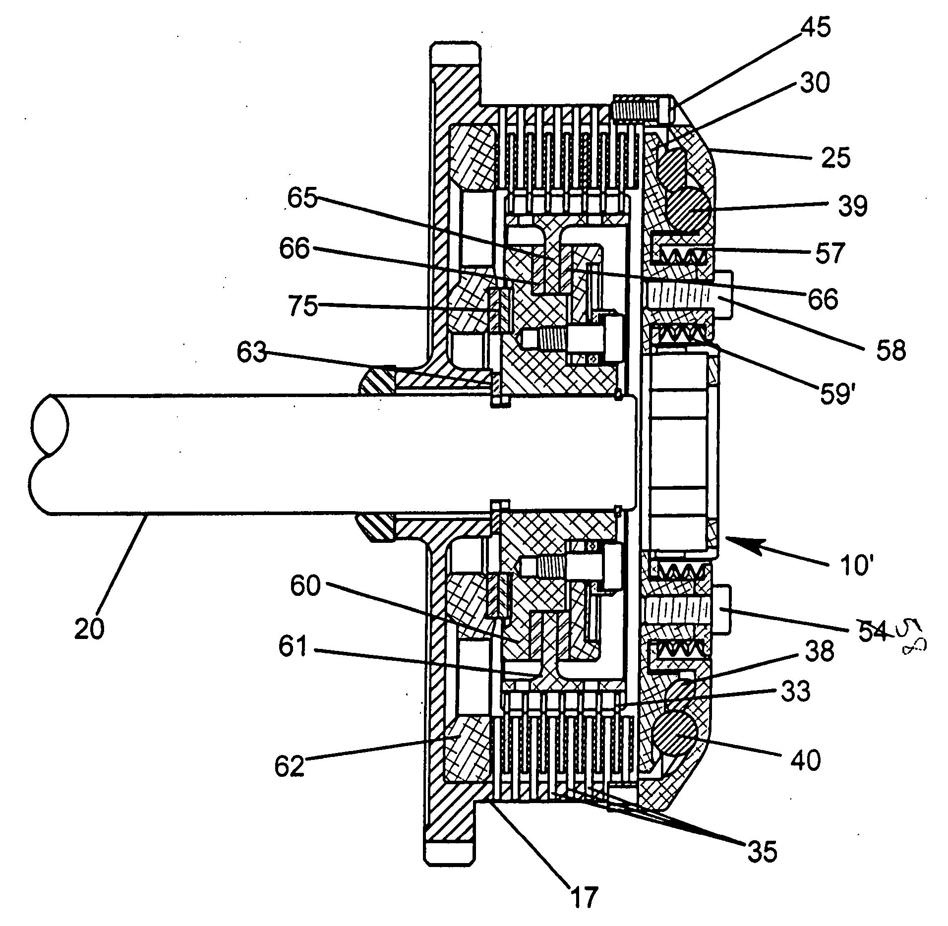
Figure 1 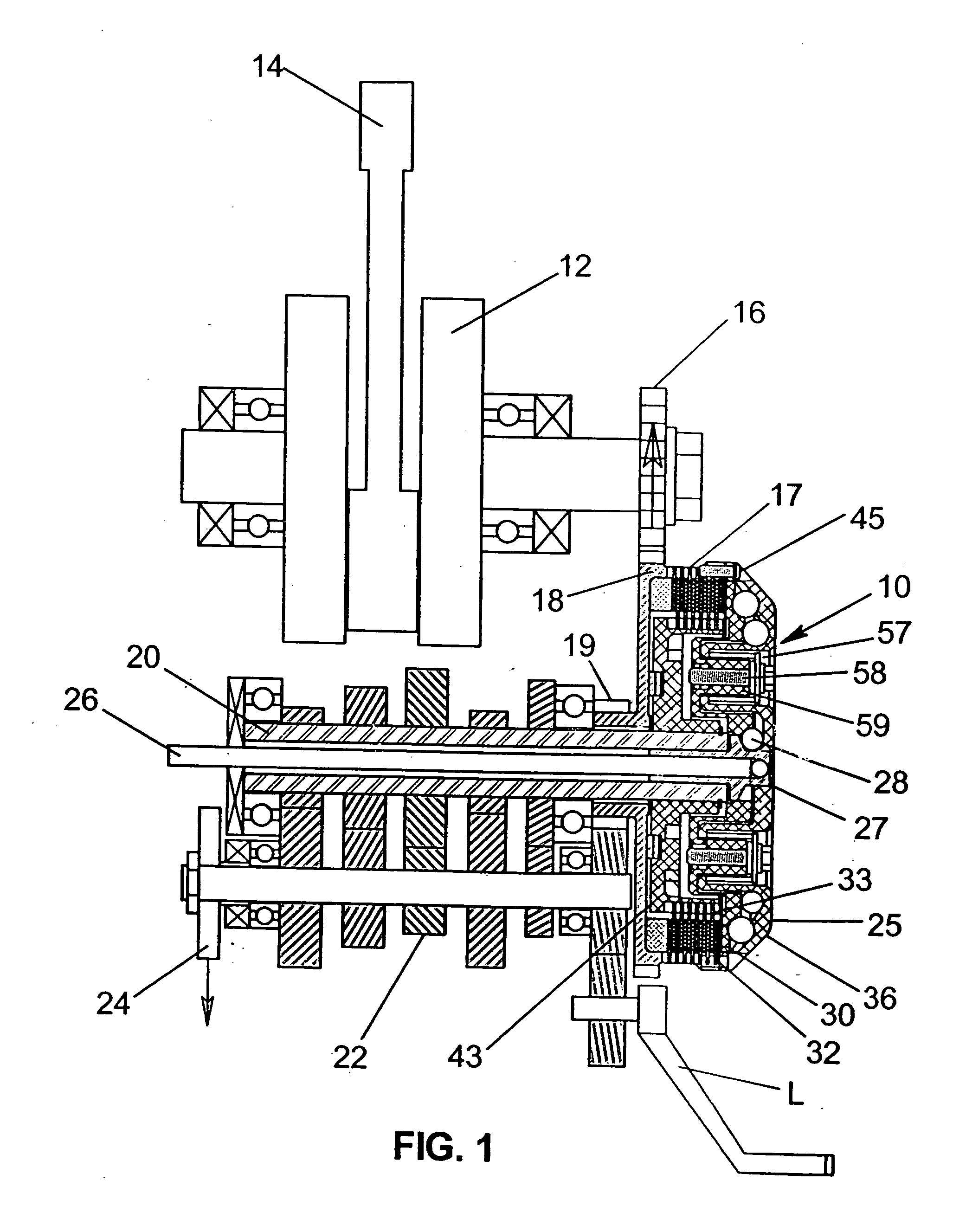
Figure 2 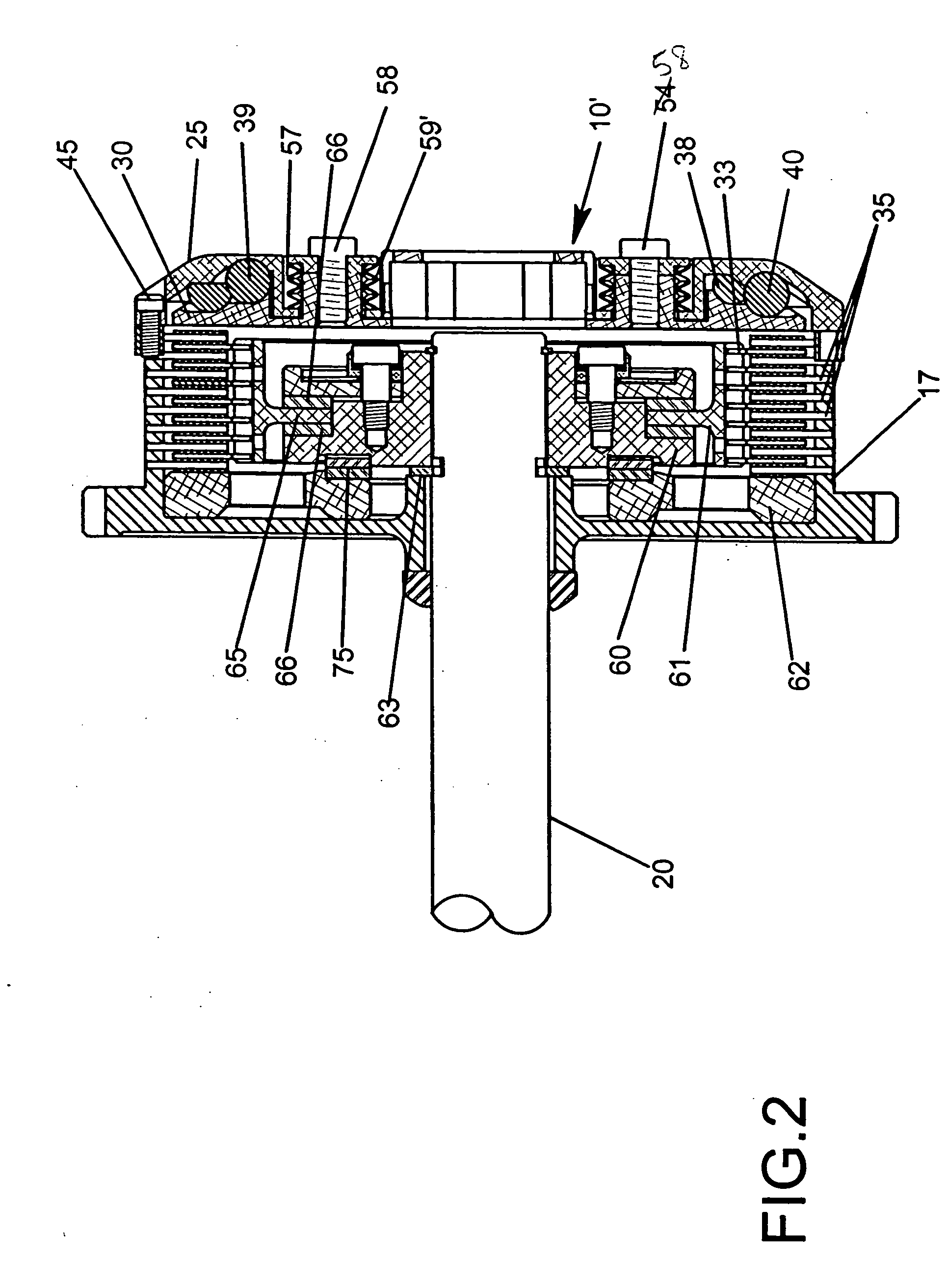
Figure 3
Abstract
Description
[0001] This application is a continuation-in-part of patent applications Ser. No. 09 / 877,518, filed Jun. 7, 2001 for AUTOMATIC CLUTCH WITH MANUAL OVERRIDE CONTROL MECHANISM by Douglas W. Drussel and George Michael Wilfley, Ser. No. 10 / 327,160, filed Dec. 20, 2002 for MULTI-ROW CAM-ACTUATED CENTRIFUGAL CLUTCH by Douglas W. Drussel and George Michael Wilfley and assigned to the assignee of this invention, and Ser. No. 10 / 791,949, filed Mar. 2, 2004 for MANUAL / AUTOMATIC PRESSURE CONTROL MECHANISM FOR CENTRIFUGAL CLUTCH, by Douglas W. Drussel and George Michael Wilfley, and assigned to the assignee of this invention, all incorporated by reference herein.BACKGROUND AND FIELD OF INVENTION
[0002] This invention relates to centrifugal clutches and more particularly relates to novel and improved centrifugal clutches having high density cam members which are urged outwardly under centrifugal force in order to activate the clutching elements.
[0003] Centrifugal clutches have been developed for m...
Examples
Embodiment Construction
[0058] FIGS. 15 to 21 illustrate a third form of invention for a motorcycle clutch 101 and having a manual override mechanism 100 comprised of a control rod 102 with hand control lever 103, cable C and a stem 104. The stem is threadedly adjustable and locked in place by a lock nut 106, according to the length of the control rod 102, so that the receiver 104 can be axially advanced into a lockout position, as shown in FIG. 15, in response to actuation of the control lever 103. Specifically, in the lockout position, the stem 104 will act through the mounting plate 110 which is anchored by a snap ring 112 to the pressure plate 114 to prevent or lock out the clutch plates 32 from engagement with the clutch plates 33. In this respect, the pressure plate 114 is biased away from the clutch plates 32 and 33 by compression springs 136. When the clutch is accelerated up to a predetermined operating speed, a series of inner and outer rows of cam members or balls 38, 39 are urged outwardly unde...