
Spherical automatic flow emergency restrictor (S.A.F.E.R.) valve
a technology of automatic flow and restrictor, which is applied in the field of valves, can solve the problems of glass being susceptible to breakage and leakage, serious fluid leakage, and high price, and achieve the effect of enduring higher pressur
Patent Information
- Authority / Receiving Office
- US · United States
- Patent Type
- Patents(United States)
- Current Assignee / Owner
- Publication Date
- 2019-10-01
Smart Images
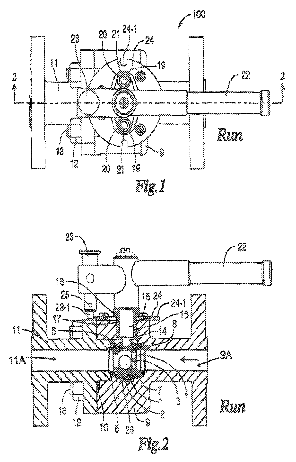
Figure 1 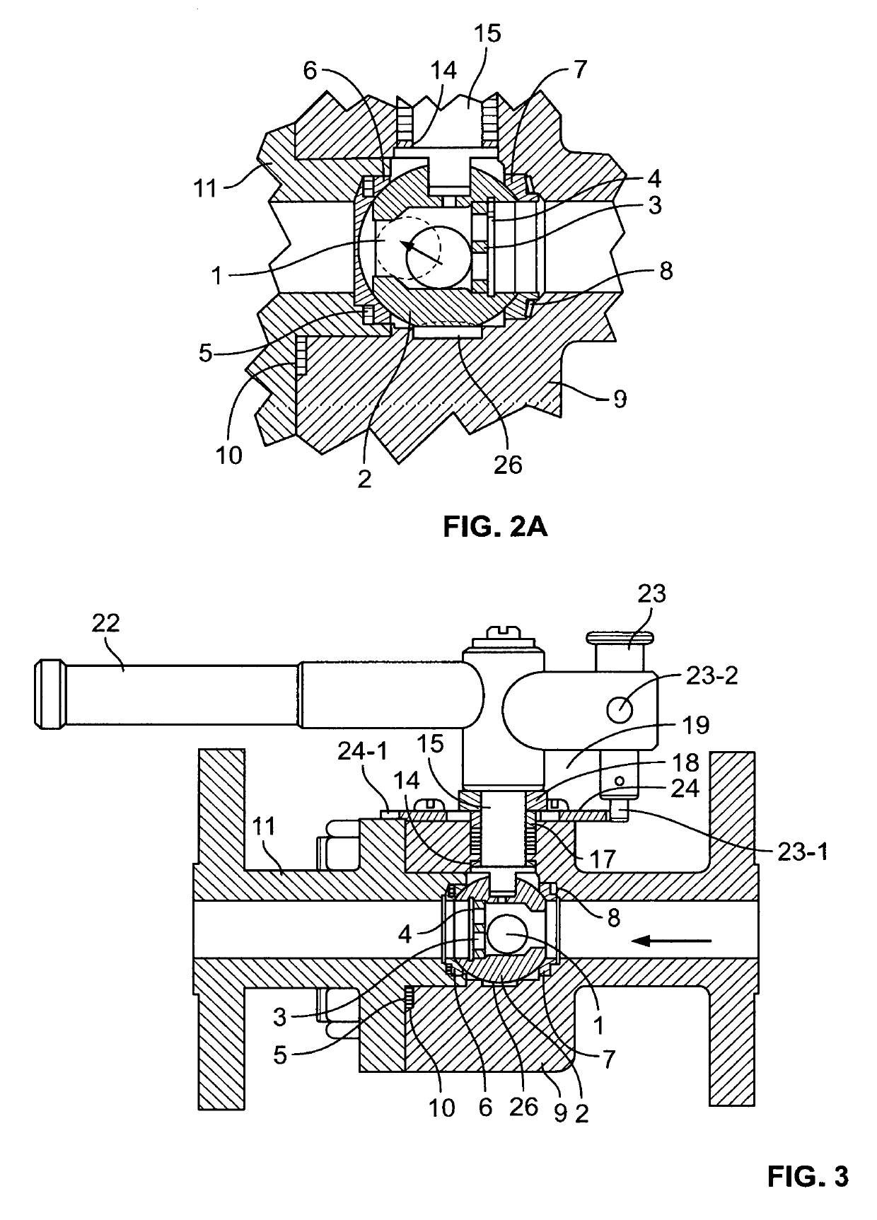
Figure 2 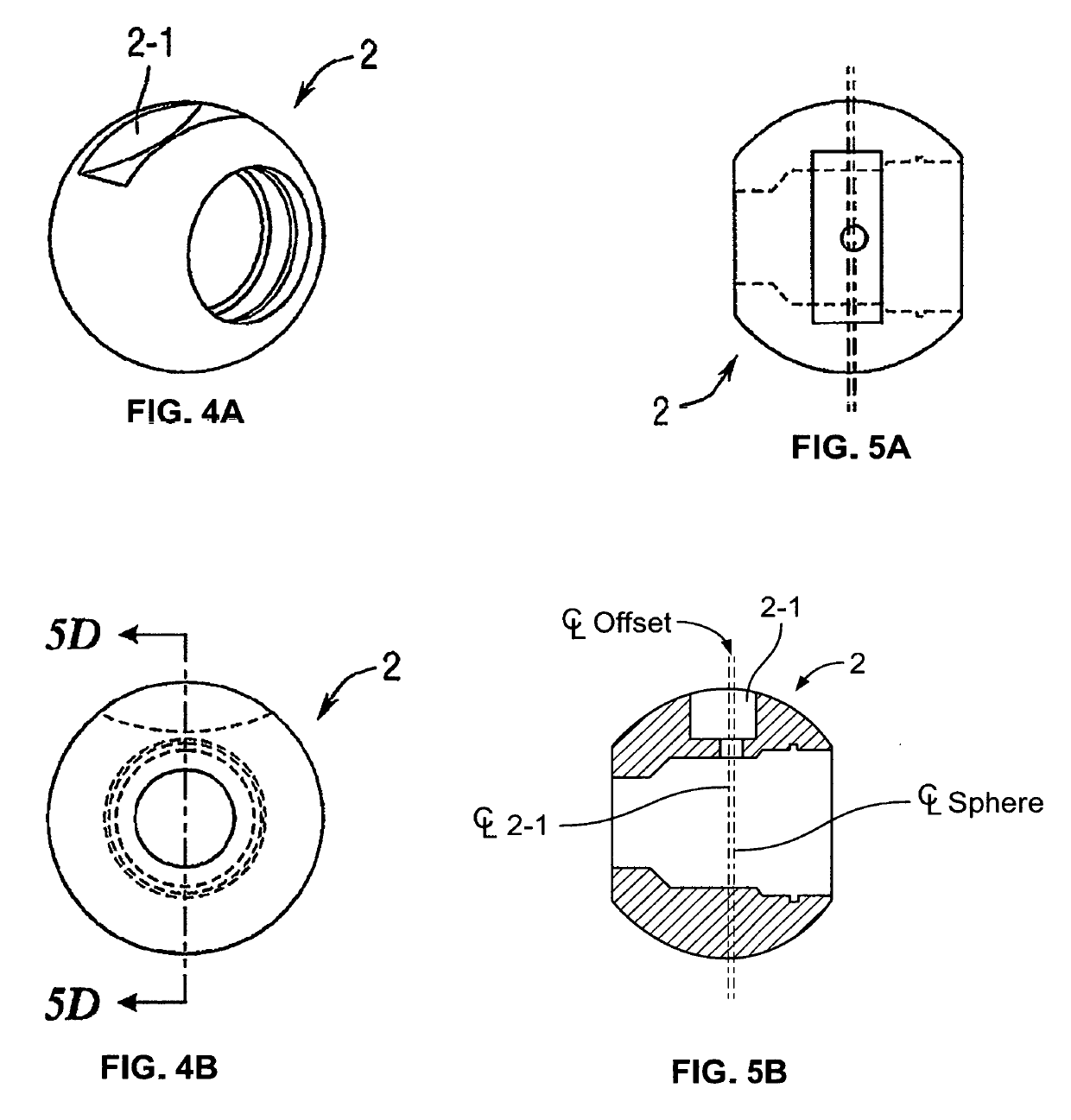
Figure 3
Abstract
Description
CROSS REFERENCE TO RELATED APPLICATIONS
[0001] The present invention is filed under 35 U.S.C. § 371 as the U.S. national phase of International Application No. PCT / US2014 / 066224, filed Nov. 18, 2014, which designated the U.S. and claims priority to U.S. patent application Ser. No. 14 / 083,418, filed Nov. 18, 2013, all of which are incorporated by reference.FIELD OF THE INVENTION
[0002] The invention relates generally to valves. In particular, the invention relates to ball check valves.BACKGROUND
[0003] In the petroleum and some other industries, it is sometimes necessary to store large quantities of heavy fluids in a large container and keep an accurate measurement of the amount of fluid within the container. In order to accomplish this task, a sight gage is often used. The level of the fluid is measured by an upper inlet passageway and lower outlet passageway which may be connected to a cylinder which may have a glass wall or window which may be calibrated to indicate the level of the flu...
Examples
Embodiment Construction
[0045]A first preferred embodiment of the invention is shown in FIGS. 1-16 with reference to the following listing of constituent parts:[0046]100 valve[0047]1 ball check[0048]2 sphere[0049]3 retainer[0050]4 retainer clip[0051]5 seat gasket[0052]6 downstream seat[0053]7 guide seat[0054]8 disc spring[0055]9 body[0056]10 body gasket[0057]11 end[0058]12 nut[0059]13 stud[0060]14 thrust washer[0061]15 stem[0062]16 stem packing[0063]17 gland ring[0064]18 gland follower[0065]19 belleville washer[0066]22 handle[0067]23 guide post[0068]24 locking plate[0069]25 stop pin
[0070]The first preferred embodiment of the valve according to the invention utilizes a body 9 and end part 11, with aligned fluid paths as shown in FIGS. 2-3. Body 9 and end 11 are of materials commensurate with the application, for example stainless steel or black oxide coated carbon steel. The valve is assembled by placing sphere 2 into a recess in body 9. The recess is formed so that the sphere 2 fluid path aligns with the f...