
Tubing saver rotator and method for using same
a rotator and tube technology, applied in the direction of drilling casings, drilling pipes, well accessories, etc., can solve the problems of tubing string wear, tubing holes, inefficient lifting or no lifting of fluids to the surface, etc., to minimize corrosion or contamination, and improve the pull strength of tubing
Patent Information
- Authority / Receiving Office
- US · United States
- Patent Type
- Applications(United States)
- Current Assignee / Owner
- Publication Date
- 2005-10-20
Smart Images
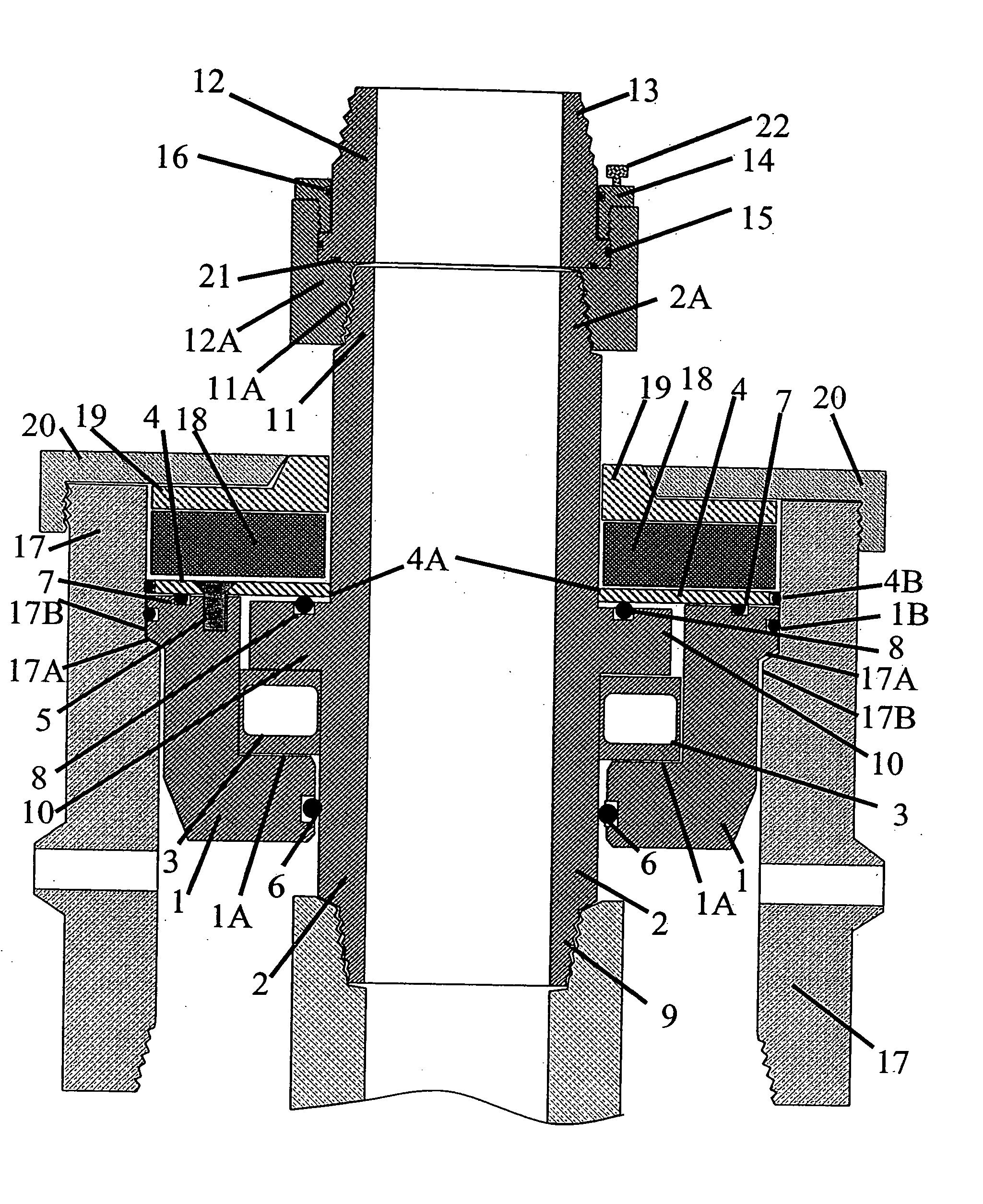
Figure 1 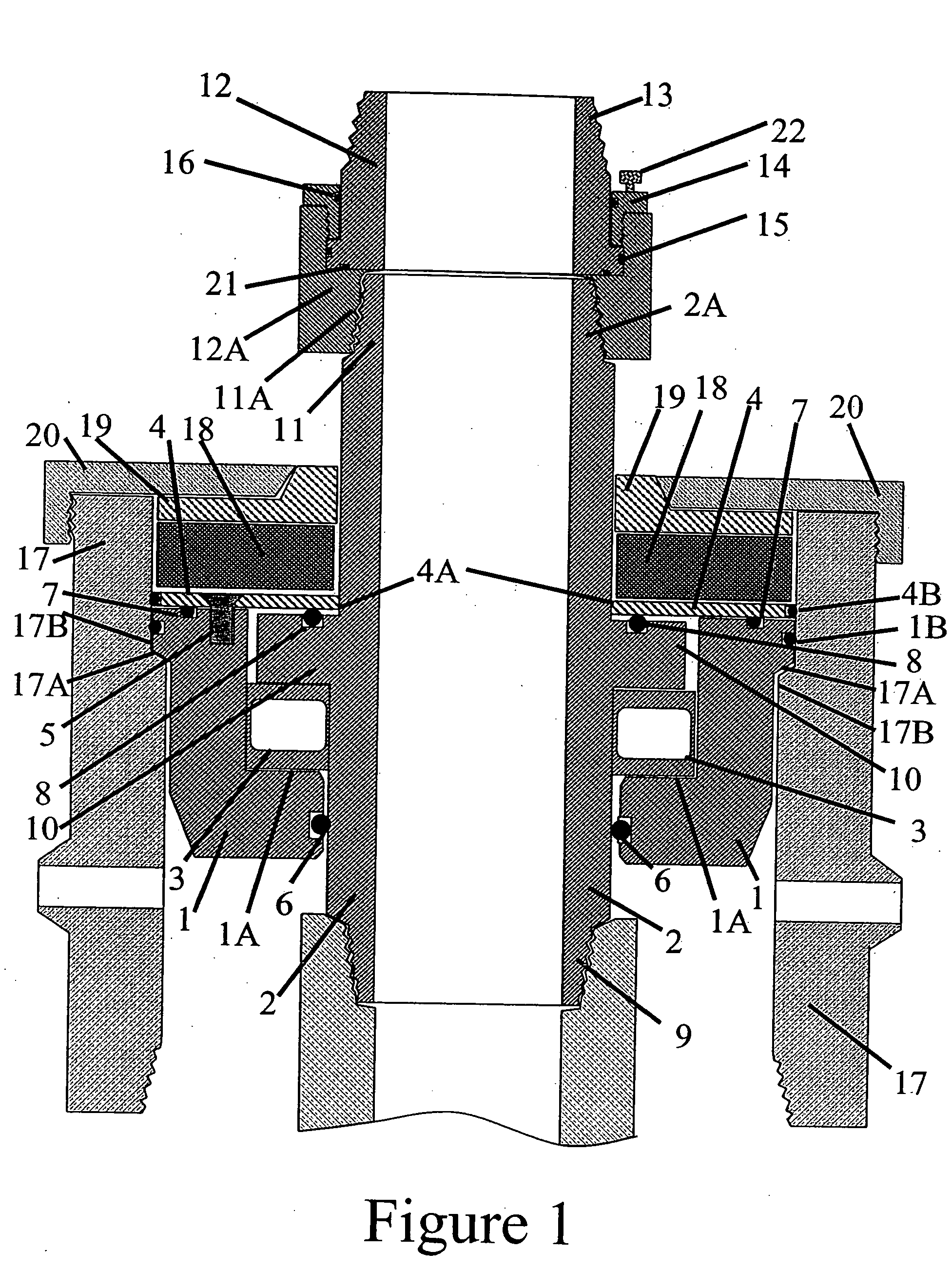
Figure 2 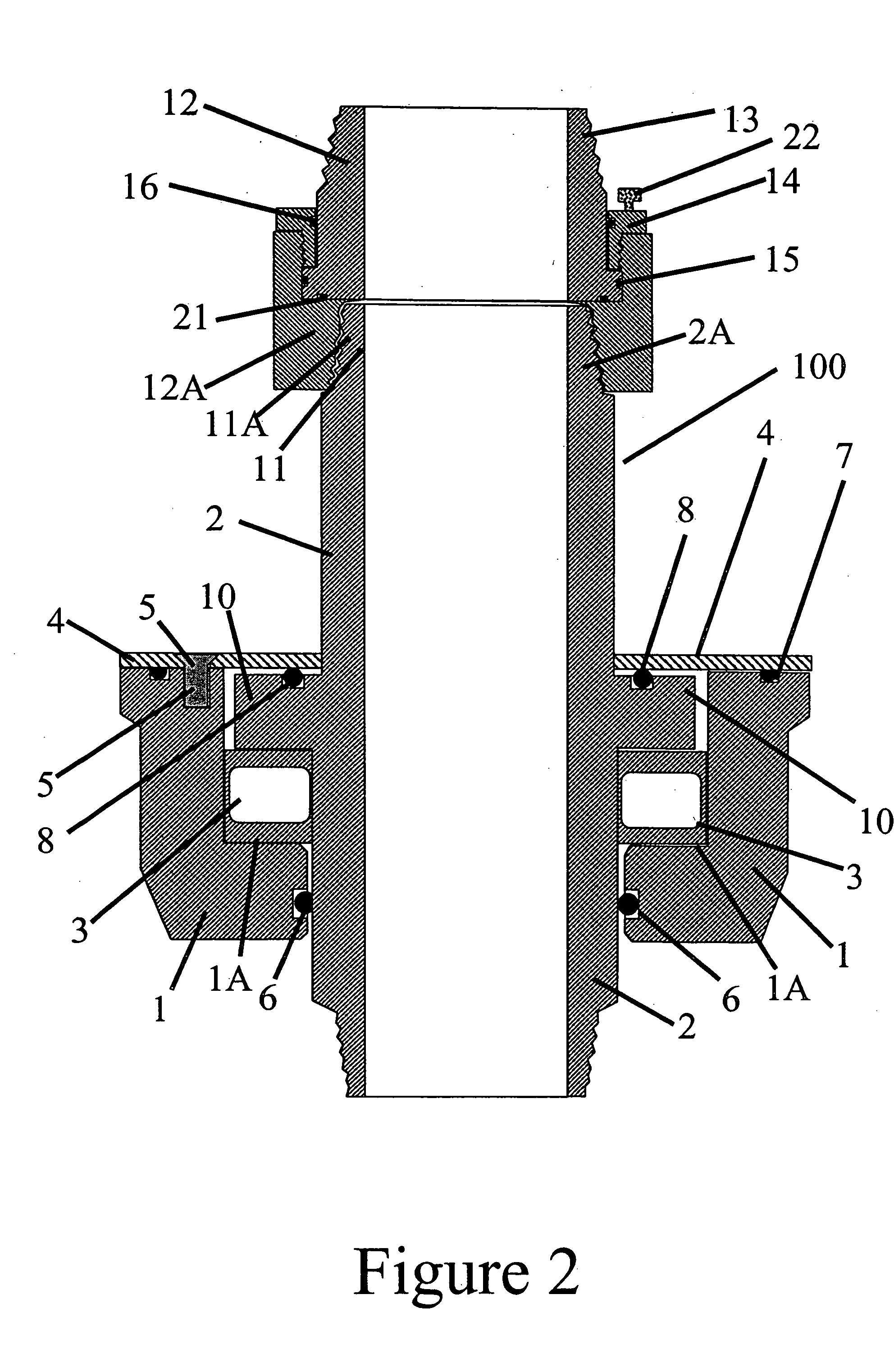
Figure 3
Abstract
Description
CROSS REFERENCES TO RELATED APPLICATIONS
[0001] U.S. Provisional Application for Patent 60 / 371,393, filed Apr. 10, 2002, with title “Tubing Saver Rotator and Method for Using Same” which is hereby incorporated by reference. Applicant claims priority pursuant to 35 U.S.C. Par. 119(e)(i). Application is also a continuation-in-part of co-pending application Ser. No. 10 / 356,750, filed Feb. 3, 2003.
[0002] Statement as to rights to inventions made under Federally sponsored research and development: Not Applicable BACKGROUND OF THE INVENTION
[0003] 1. Field of the Invention
[0004] This invention relates to a tubing rotator assembly that sits inside a casing head for purposes of suspending and rotating the tubing string in an oil well.
[0005] 2. Brief Description of Prior Art
[0006] A typical wellhead is often comprised of a casing head which engages or is otherwise mounted to a casing string contained within a wellbore of a well at the surface. A mandrel bowl is mounted to the casing head ...
Examples
Embodiment Construction
[0025]FIGS. 1-4 illustrate a preferred embodiment of a tubing saver rotator assembly 100 made in accordance with the present invention. Generally, the present invention is an apparatus for attachment in an existing casing head or a casing head modified to accept a bowl or ledge assembly. This apparatus having a surface, such as a bearing in which a tubing mandrel rests and allows one to rotate the tubing above the wellhead. It provides a low profile reducing the distance between the casing head and the pumping tee, which may eliminate the need for one to raise the pumping unit to fit on the rotator. In addition, the conventional seals above the bowl assembly have less chance of leaking fluids located between the casing and tubing due to the seals potentially installed in the present invention. In addition, if the conventional seals do start to leak, one can change the sealing elements without having to remove the pump tee, tubing rotator assembly 100 or tubing string (not shown) fro...