
Forged roller
Patent Information
- Authority / Receiving Office
- US · United States
- Current Assignee / Owner
- Publication Date
- 2006-01-19
Smart Images
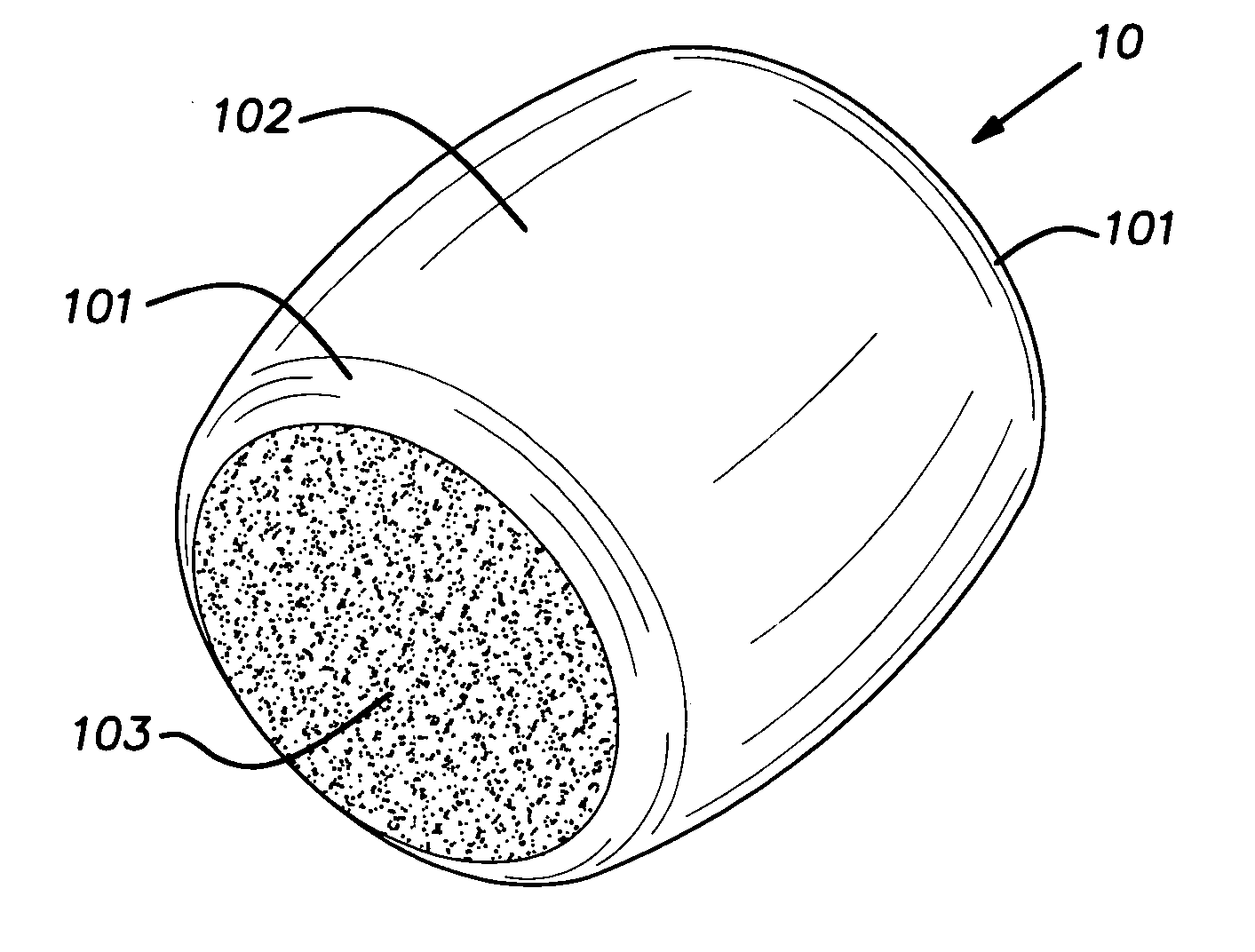
Figure 1 
Figure 2 
Figure 3
Abstract
Description
BACKGROUND OF THE INVENTION
[0001] The invention relates to the manufacture of cold-formed rollers and, in particular, to a process, machine and tooling that affords improvements in roller quality and reduction in manufacturing costs. PRIOR ART
[0002] Rollers used in anti-friction bearings are commonly initially made in cold-forming machines. Traditionally, the cold-formed pieces are subsequently machined by grinding processes to achieve a desired precision shape and finish. Typically, grinding operations may involve several steps because the cold-formed part has significant flash and / or excess material as a result of the limitations and characteristics of traditional methods and tooling used in the cold-forming art. Grinding processes are expensive and significantly add to the cost of the finished roller. SUMMARY OF THE INVENTION
[0003] The invention involves a cold-formed metal roller blank, that is relatively close to the net shape of a finish ground roller thereby greatly reduci...
Examples
Embodiment Construction
[0014]FIG. 1 illustrates an example of a cold-formed roller blank 10 made in accordance with the present invention. The roller blank is of the barrel type, but it will be appreciated that certain principles of the invention are applicable to other roller styles including cylindrical and tapered rollers. The roller blank 10 made by the processes and tools disclosed hereinbelow can be produced to dimensional tolerances that are reduced to about 1 / 10 of that which is presently commercially accepted for subsequent finishing, typically by grinding after heat treatment. The roller blank 10 after heat treating and grinding is typically used with multiple identical pieces in anti-friction bearing assemblies as known in the art.
[0015] The roller 10 is formed in a multistation progressive cold-forming machine 11 illustrated in FIG. 3 and of a type generally known in the industry. The forging machine 11 is depicted in a plan view of the tooling area in FIG. 3. The machine 11 includes a quill ...