
Clamping device for a steering column
a technology of a clamping device and a steering column, which is applied in the direction of steering column, steering parts, vehicle components, etc., can solve the problems of high production cost, complicated second disc, and high production cost of the clamping device disclosed in u.s. pat. no. 5,394,767, so as to improve the safety of the driver of the motor vehicle, enhance the operation safety, and ensure the effect of safety
Patent Information
- Authority / Receiving Office
- US · United States
- Patent Type
- Applications(United States)
- Current Assignee / Owner
- Publication Date
- 2006-09-28
- Estimated Expiration
- Not applicable · inactive patent
Smart Images
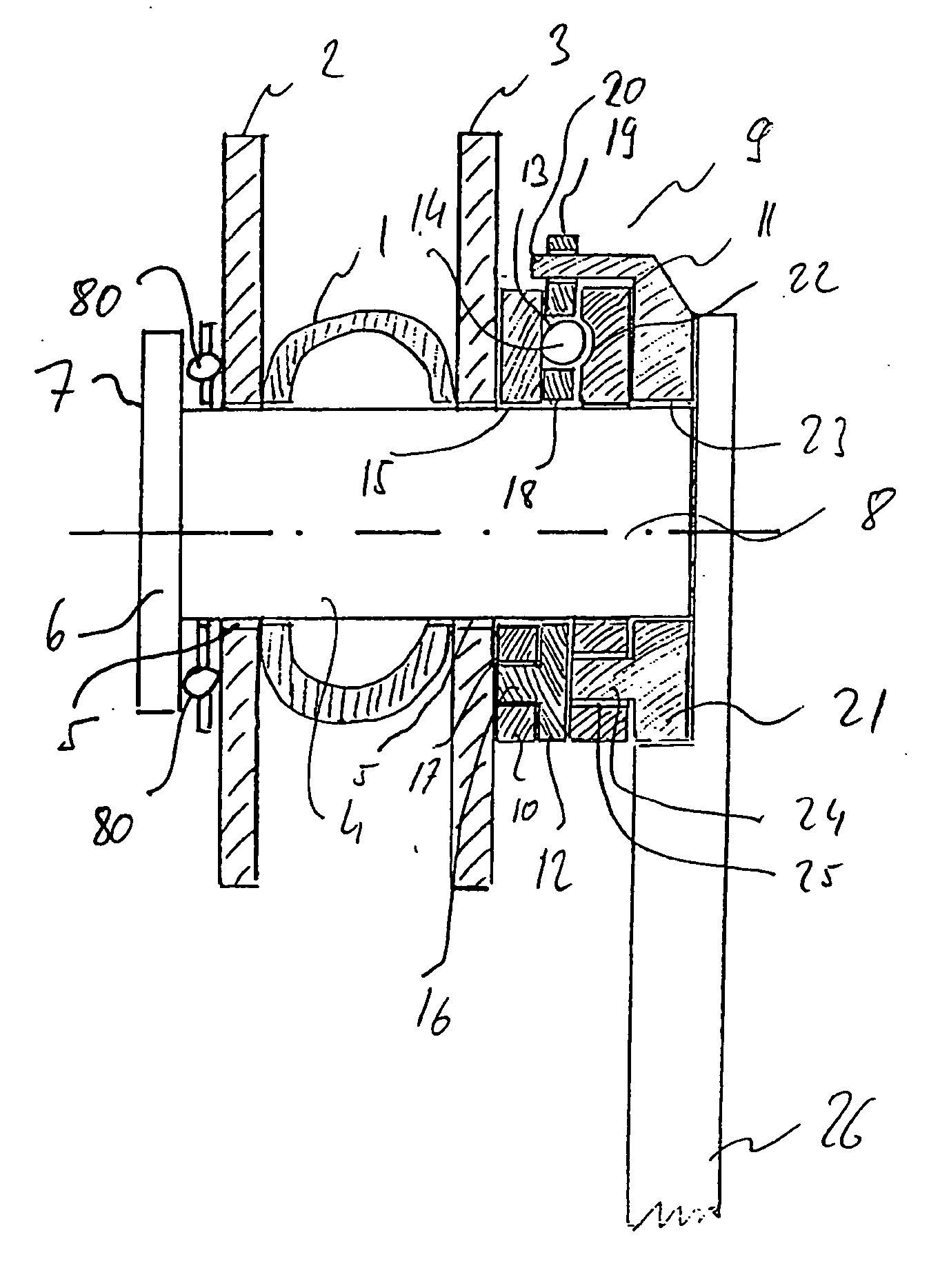
Figure 1 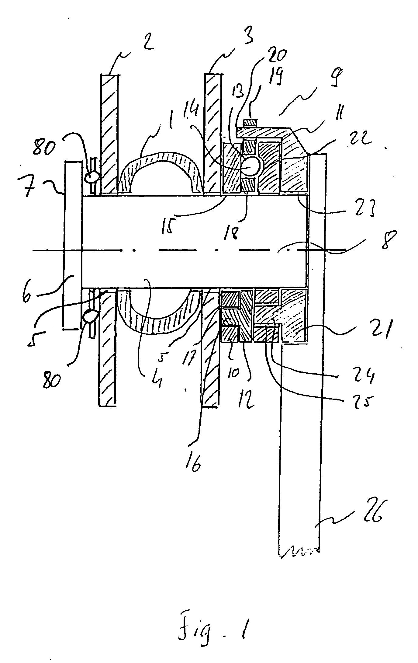
Figure 2 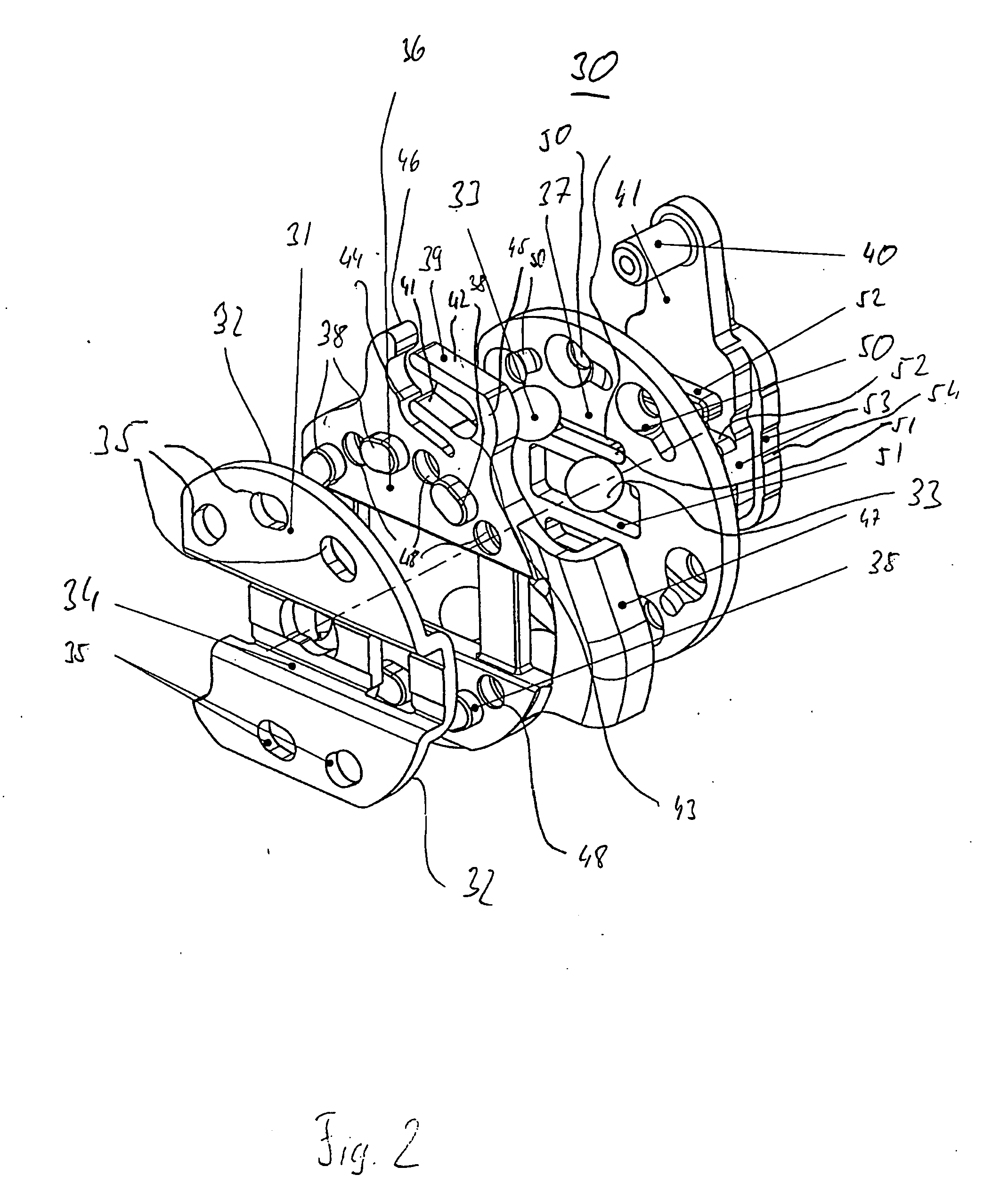
Figure 3
Abstract
Description
FIELD OF THE INVENTION
[0001] The present invention relates to a clamping device for fixing the position of a vehicle steering column which is adjustable in length and / or inclination, in particular a motor vehicle steering column. TECHNOLOGICAL FIELD
[0002] Steering column position adjusting devices with which the inclination as well as the length of the steering column can be adjusted, i.e. the position of the steering wheel in relation to the operator is adjustable, are used to improve driving comfort and achieve individual adaptation of the steering wheel position to the requirements of the driver of the vehicle.
[0003] Furthermore, steering column position adjusting devices are known with which height adjustment of the steering column is achievable so that it becomes possible for vehicle drivers of different build to optimally adjust the steering wheel to suit their needs and the particular driving situation. These clamping devices not only improve the comfort but also the safet...
Examples
Embodiment Construction
[0021]FIG. 1 shows a position adjusting device for a steering column 1, in particular of a motor vehicle, which position adjusting device is arranged between a first supporting arm 2 and a second supporting arm 3. The supporting arms 2 and 3 form part of a fixed bracket (not shown in FIG. 1) in the region of the instrument panel of a motor vehicle. A tie bolt 4 is provided between the first supporting arm 2 and the second supporting arm 3, which tie bolt 4 is arranged at a right angle in relation to the steering column 1. Preferably the tie bolt 4 is a cylindrical bolt. The tie bolt 4 leads through apertures 5 in the first and second supporting arms 2, 3. For the purpose of attaching the tie bolt 4, on one end 6 of the tie bolt a region 7 is provided where the diameter is larger than the diameter of the aperture or borehole 5 in the supporting arm 2. Through the region with larger diameter 7, the tie bolt 4 is held in axial direction, in FIG. 4 towards the right, to the first suppor...