
Oil strainer structure of engine and oil return structure of engine
a technology of oil strainer and engine, which is applied in the direction of pressure lubrication, lubricant mounting/connection, lubrication elements, etc., can solve the problems of significant limitation in flexibility in positioning difficult to secure a sufficient area of the strainer, and difficult to arrange the oil suction hole, etc. achieve the effect of reliably performing gas-liquid separation, high flexibility, and enhancing flexibility in position determination
Patent Information
- Authority / Receiving Office
- US · United States
- Patent Type
- Applications(United States)
- Current Assignee / Owner
- Publication Date
- 2008-02-28
- Estimated Expiration
- Not applicable · inactive patent
Smart Images
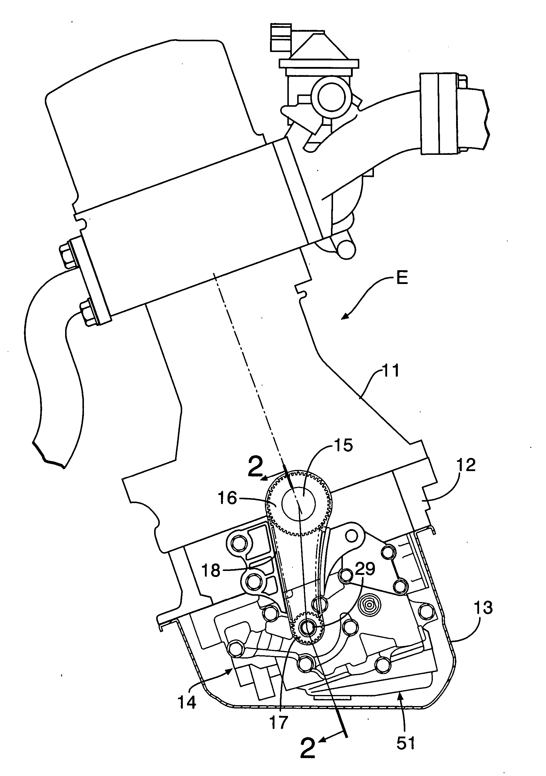
Figure 1 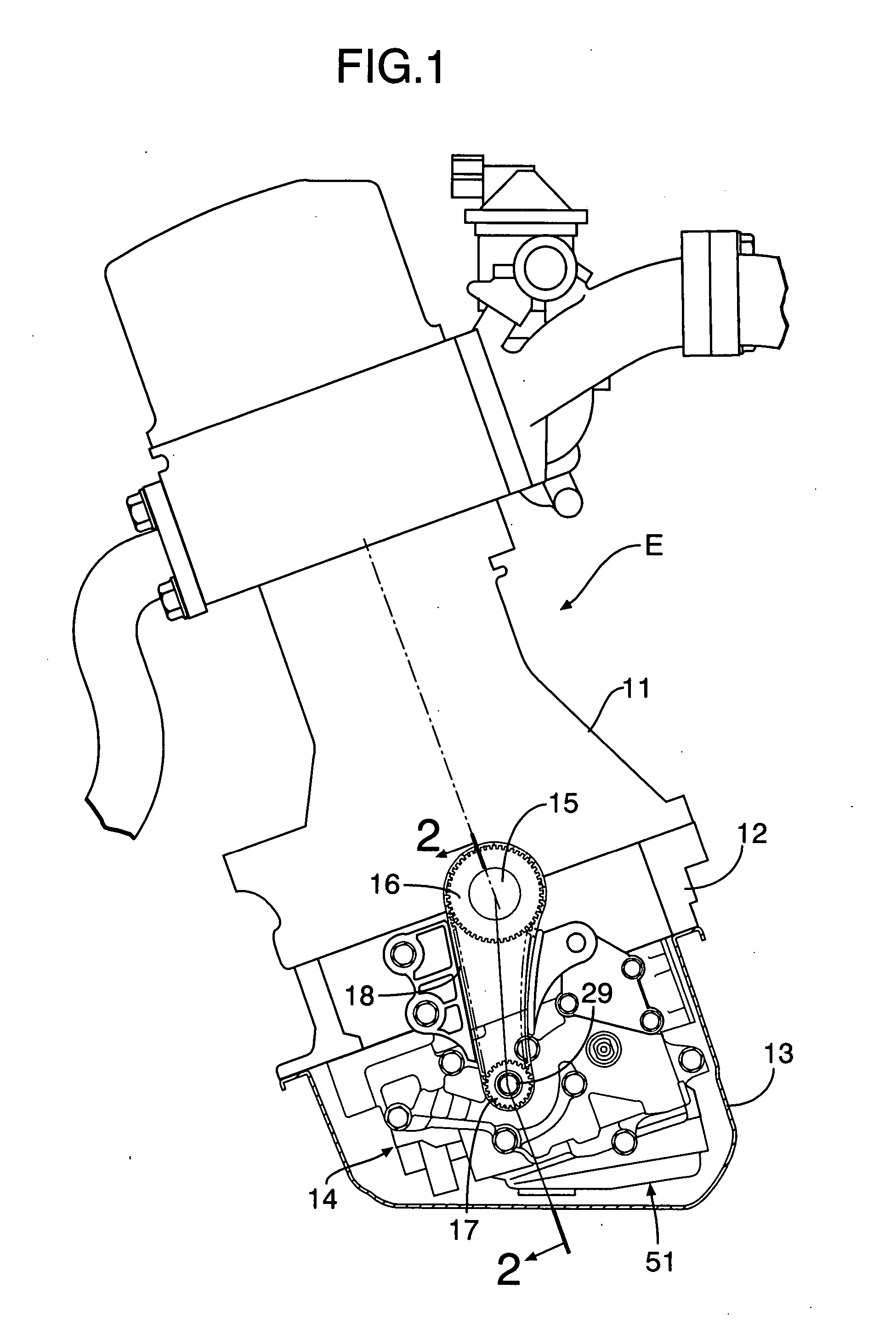
Figure 2 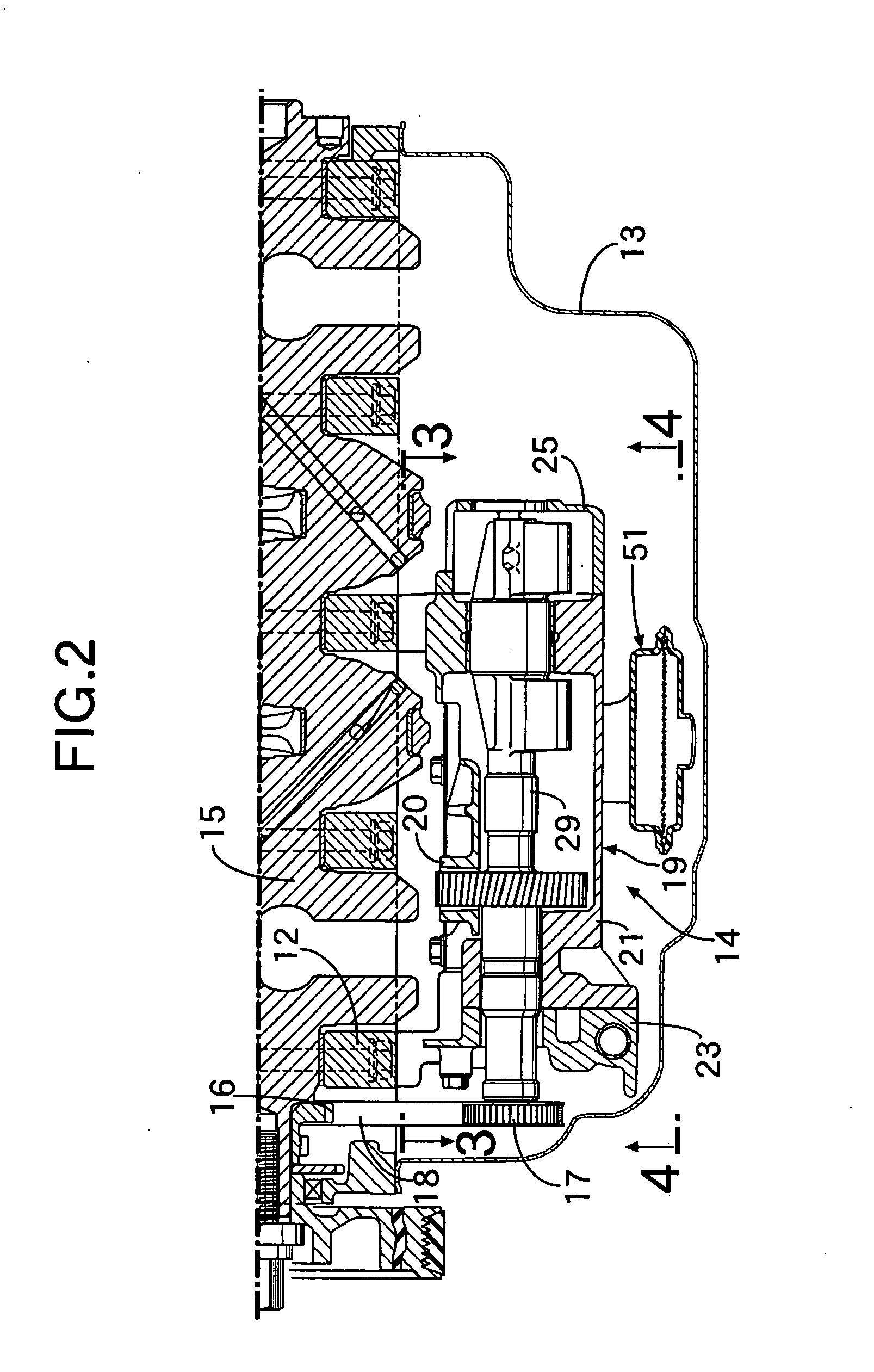
Figure 3
Abstract
Description
RELATED APPLICATION DATA
[0001] The Japanese priority application Nos. 2006-230199, 2006-230200, 2006-230201 and 2006-230202 upon which the present application is based are incorporated in their entirety herein by reference. BACKGROUND OF THE INVENTION
[0002] 1. Field of the Invention
[0003] The present invention generally relates to an oil strainer structure of an engine, which includes an oil strainer for filtering oil in an oil pan, the oil strainer being arranged between a balancer housing and the oil pan of the engine and supported by the balancer housing.
[0004] Also, the present invention generally relates to an oil return structure of an engine, which includes an oil return member for returning oil separated from blowby gas to an oil pan, the oil return member being arranged between a balancer housing and the oil pan of the engine.
[0005] 2. Description of the Related Art
[0006] Japanese Patent Application Laid-open No. 2001-74105 discloses an oil strainer structure of an en...
Examples
first embodiment
[0046] the present invention will be described with reference to FIGS. 1 to 9.
[0047]FIGS. 1 and 2 show the following structural arrangement. A lower block 12 is fixed to a lower surface of a cylinder block 11 of a diesel engine E of an automobile. An oil pan 13 is fixed to the lower surface of the lower block 12. Provided on a lower surface of the lower block 12 is a balancer device 14 which reduces secondary vibration of the engine E, and which is housed in the oil pan 13. A crankshaft 15 is rotatably supported between the cylinder block 11 and the lower block 12. A drive sprocket 16 is provided at an end of the crankshaft 15. A driven sprocket 17 is provided at an end of a drive balancer-shaft 29 of the balancer device 14. An endless chain 18 is wound around the drive and driven sprockets 16 and 17.
[0048] FIGS. 3 to 6 show the following structural arrangement. The balancer device 14 has a balancer housing 19 including an upper housing part 20 and a lower housing part 21. The uppe...