
Method of and apparatus for in-situ measurement of changes in fluid composition by electron spin resonance (ESR) spectrometry
Patent Information
- Authority / Receiving Office
- US · United States
- Current Assignee / Owner
- Publication Date
- 2008-07-10
Smart Images
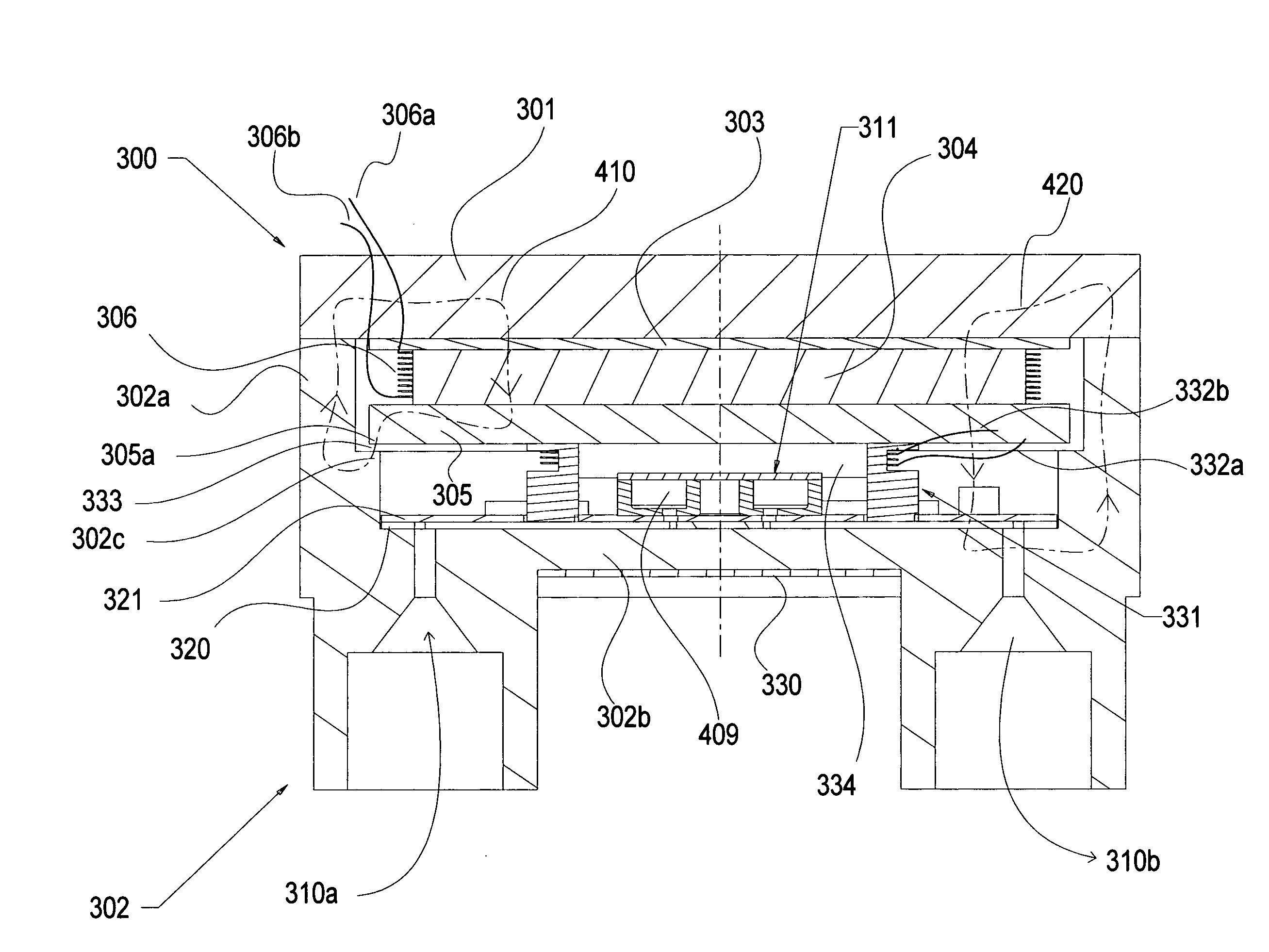
Figure 1 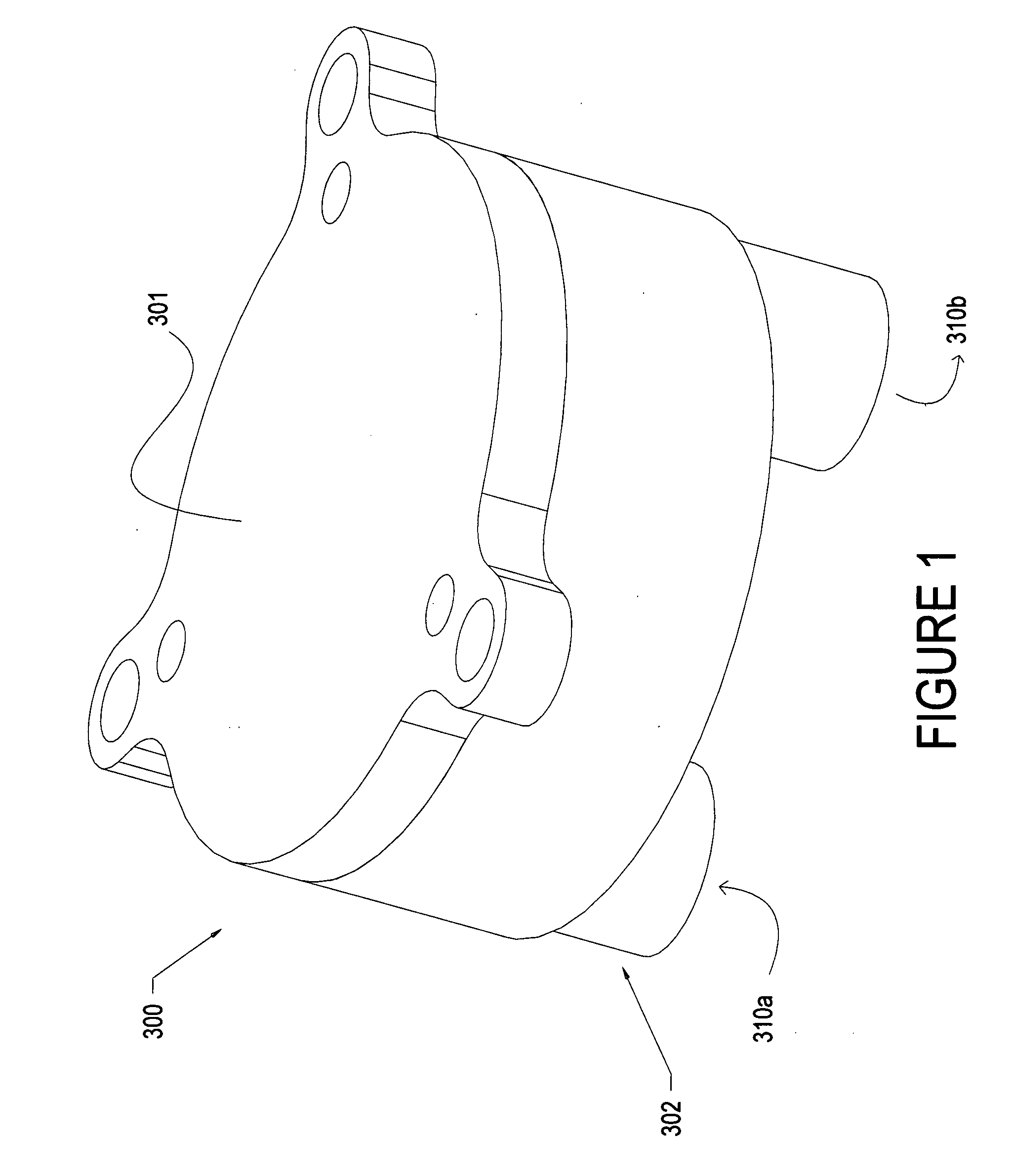
Figure 2 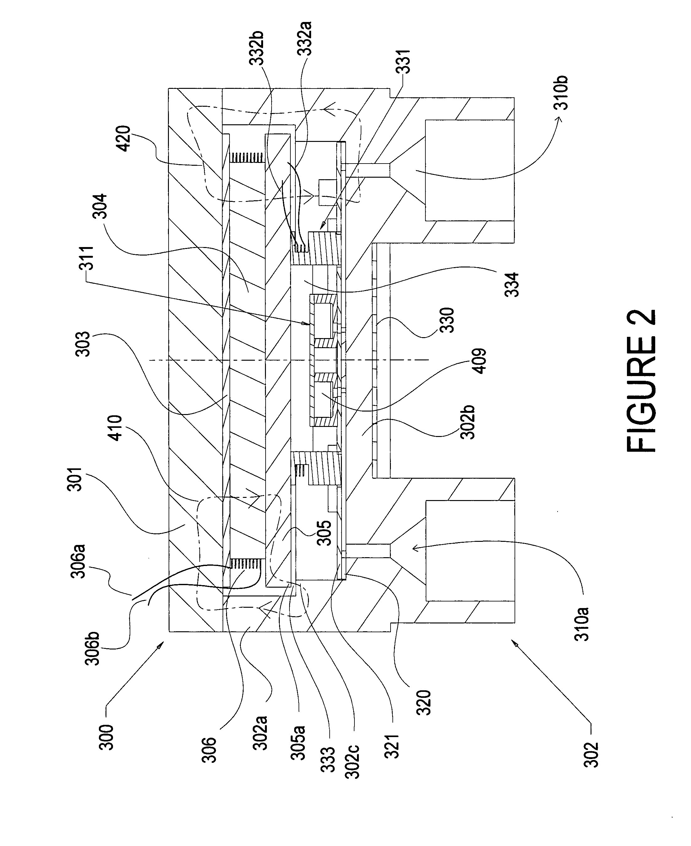
Figure 3
Abstract
Description
STATEMENT REGARDING FEDERALLY FUNDED RESEARCH
[0001] Federal funds were used in the development of the cavity structure improvements underlying this invention under Contract No. W56 HZV-06-C-0582 awarded by the U.S. Army, this application being a continuation-in-part of parent U.S. application Ser. No. 11 / 590,522, filed Oct. 31, 2006 for Method Of And Apparatus For In-Situ Measurement Of Degradation Of Automotive Fluids And The Like by Micro-Electron Spin Resistance (ESR) Spectrometry.FIELD OF THE INVENTION
[0002] The invention relates to the field of electron spin resonance (ESR) spectrometry, and more particularly to the use of such technology for measuring and diagnosing the real-time degradation or changes in fluid composition during use in operating, machinery such as of automotive engine oil and the like, in situ and during operating engine conditions and environments, as more particularly described in said parent application.BACKGROUND OF THE INVENTION
[0003] As explained in said p...
Examples
Embodiment Construction
[0040]FIGS. 1 and 2 show the sensor 300 of this continuation-in-part invention, with its encasing structure 302, with a bottom 302b, cylindrical sides 302a and a top wall 301. Top 301 has attached to it, for example by bonding, a non-magnetic shim such as a brass shim 303, FIG. 2, to which is then bonded axially poled cylindrical magnet 304 and pole piece 305. Coil 306, with leads 306a and 306b, circumferentially surrounds the magnet 304. As current is applied to the coil leads, the generated magnetic field interacts with the filed of the permanent magnet to slowly vary the net magnetic field that travels uniformly through the system. The first magnetic field path 410 (shown in the dash-line left-side loop in FIG. 2) travels axially into pole piece 305 and then radially out to the perimeter 305a of the pole piece. The field lines cross the gap 333 and cross into the step feature 302c of the cavity sidewall 302a. This small overlap region causes the field to saturate inside the metal...