
Apparatus for and method of withdrawing ions in EUV light production apparatus
Patent Information
- Authority / Receiving Office
- US · United States
- Current Assignee / Owner
- Publication Date
- 2009-10-22
Smart Images
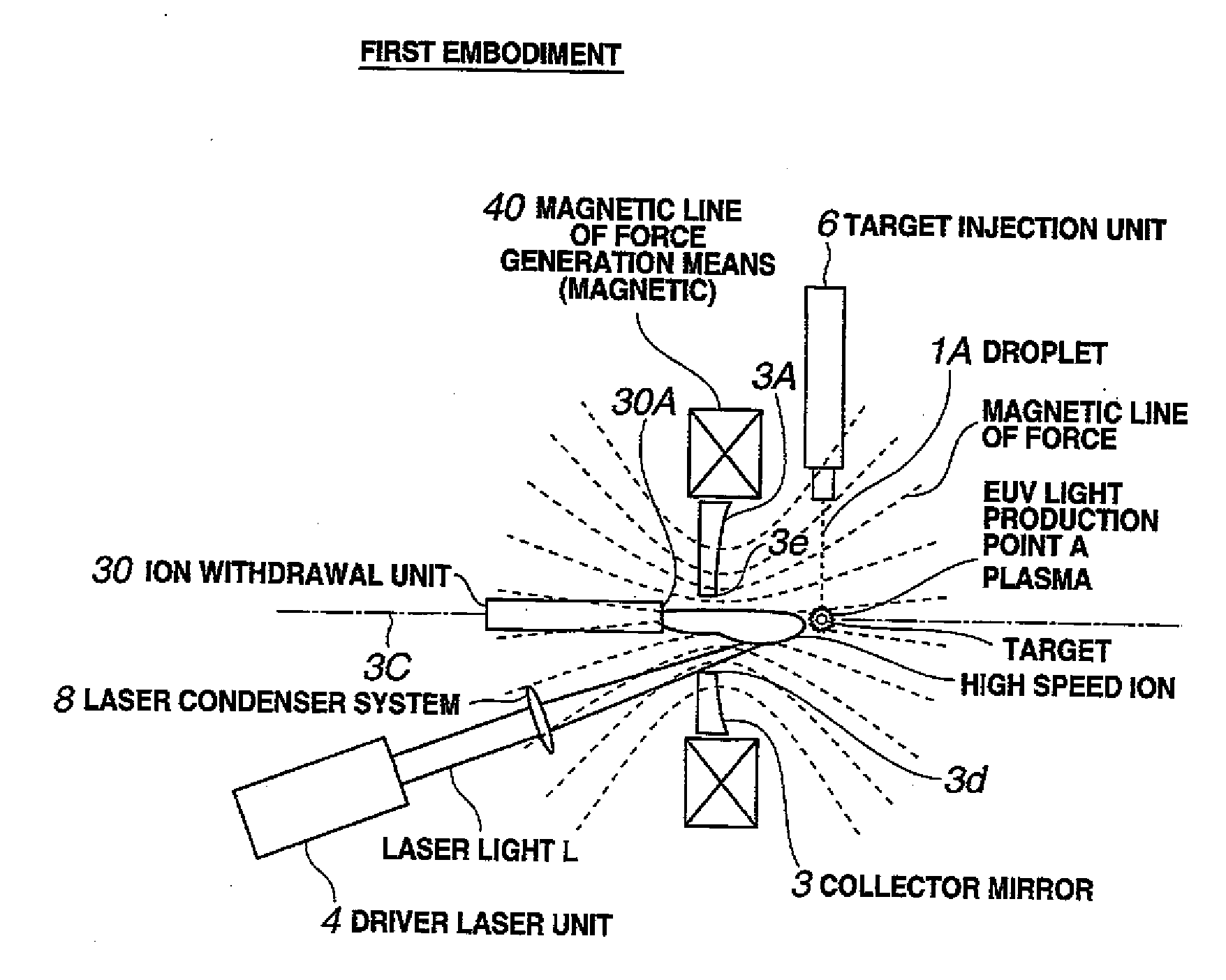
Figure 1 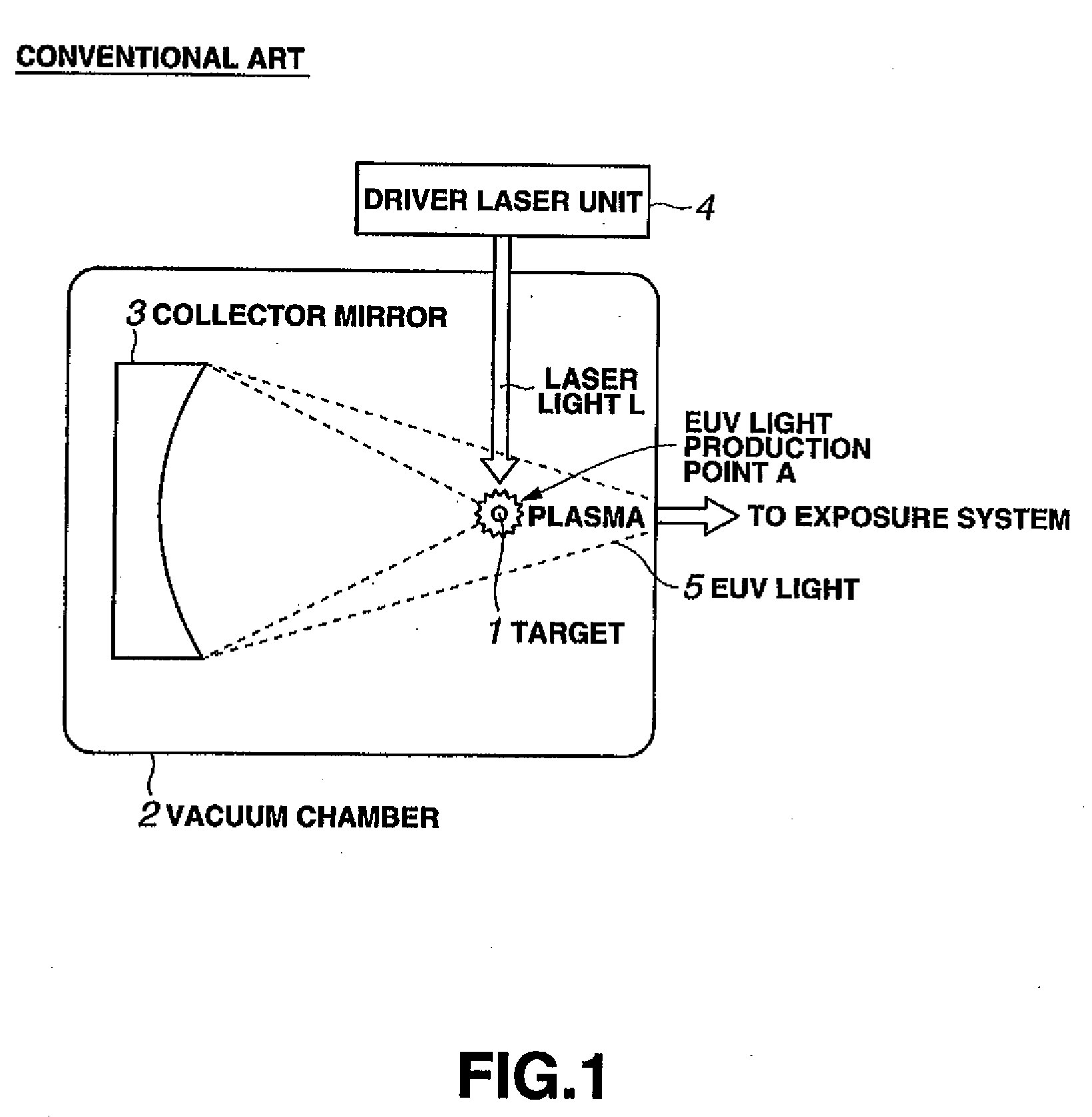
Figure 2 
Figure 3
Abstract
Description
BACKGROUND OF THE INVENTION
[0001] 1. Field of the Invention
[0002] The present invention relates to an EUV light production apparatus that is used as a light source for an exposure system and so on, and particularly, to an apparatus for and a method of withdrawing ions emitted from a target that has been made in a plasma state at an EUV light production point.
[0003] 2. Description of Related Art
[0004] A light lithography technique, in which a circuit pattern is optically transferred on a semiconductor wafer, is important for realizing the integration in an LSI. As an exposure system used for light lithography, one that employs a reduced projection exposure method, i.e. a stepper, is utilized at present. Specifically, a light transmitted through an original image (reticule) pattern irradiated with a light source is projected on a light-sensitive material on a semiconductor substrate via a reduced projection optical system to form a circuit pattern. The resolution of the projected image is...
Examples
first embodiment
[0076]FIGS. 4A through 4C are views showing a configuration of an apparatus according to a first embodiment. FIG. 4A shows the overall configuration of the apparatus, and FIGS. 4B and 4C show a reflection plane 3A of a collector mirror 3.
[0077]The EUV light production apparatus shown in FIG. 4A has a target 1 located on EUV light production point A in a plasma state to allow it to produce EUV light and output it outside, like the apparatus shown in FIG. 1.
[0078]The EUV light production apparatus employs an LLP method and is used as a light source for an exposure system (not shown).
[0079]Specifically, a collector mirror 3 for collecting EUV light is provided inside a vacuum chamber 2 (not shown) of the EUV light production apparatus. The EUV light collected by the collector mirror 3 is transmitted to the exposure system provided outside the vacuum chamber 2, like the apparatus shown in FIG. 1. The exposure system is a system for forming semiconductor circuit patterns on a semiconduct...
second embodiment
[0120]FIGS. 7A and 7B show configurations of an apparatus according to a second embodiment.
[0121]In the second embodiment, a supplementary magnet 45 or a supplementary core 46 as magnetic force production means for further converging the magnetic lines of force at the entrance 30A of the ion withdrawal unit 30 to make the flux density higher is additionally provided.
[0122]FIG. 7A shows an apparatus obtained by adding the supplementary magnet 45 to the apparatus of the first embodiment as described above.
[0123]The supplementary magnet 45 surrounds the entrance 30A of the ion withdrawal unit 30 and is disposed so as to apply a magnetic field to a small space in the vicinity of the entrance 30A. The supplementary magnet 45 further converges the magnetic lines of force at the entrance 30A of the ion withdrawal unit 30 to make the flux density higher. The size of the supplementary magnet 45 can be minimized even if the flux density thereof is equal to or larger than that of the magnet 40...
third embodiment
[0128]FIGS. 8A and 8B are views showing configurations of an apparatus according to a third embodiment.
[0129]FIGS. 8A and 8B each show an apparatus obtained by modifying the position of the magnet 40 in the first embodiment.
[0130]The magnet 40 is disposed around the periphery of the collector mirror 3 in the first embodiment while the magnet 40 in the third embodiment is disposed on the opposite side of the collector mirror 3 from the EUV light production point A. In other words, the magnet 40 is provided so as to surround the entrance 30A of the ion withdrawal unit 30.
[0131]The magnet 40 of the apparatus shown in FIG. 8A can be smaller than that of the apparatus of the first embodiment However, it is necessary for the magnet 40 to have a hole 40a that allows the laser light L to pass therethrough.
[0132]Since the magnet 40 is provided to surround the entrance 30A of the ion withdrawal unit 30, the magnet 40 can be miniaturized while the flux density same as that of the apparatus of ...