
Glide-Angle Light for Approach Guidance of Aircraft
a technology of aircraft approach and angle light, which is applied in the direction of portable electric lighting, non-electric lighting, light and heating equipment, etc., can solve the problems of high cost, and achieve the effect of producing well cross-sectional restriction
Patent Information
- Authority / Receiving Office
- US · United States
- Current Assignee / Owner
- Publication Date
- 2010-02-11
- Estimated Expiration
- Not applicable · inactive patent
Smart Images
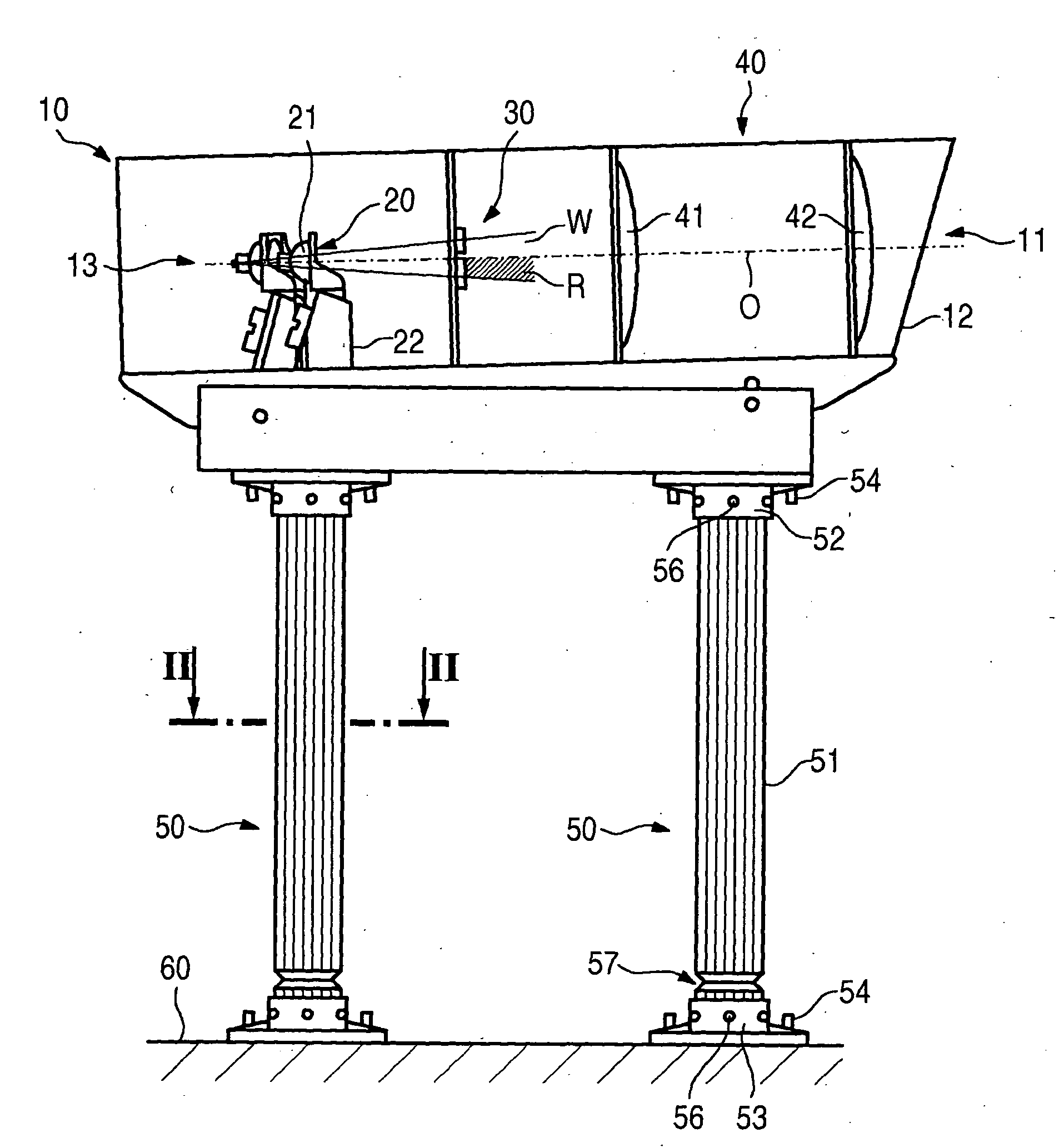
Figure 1 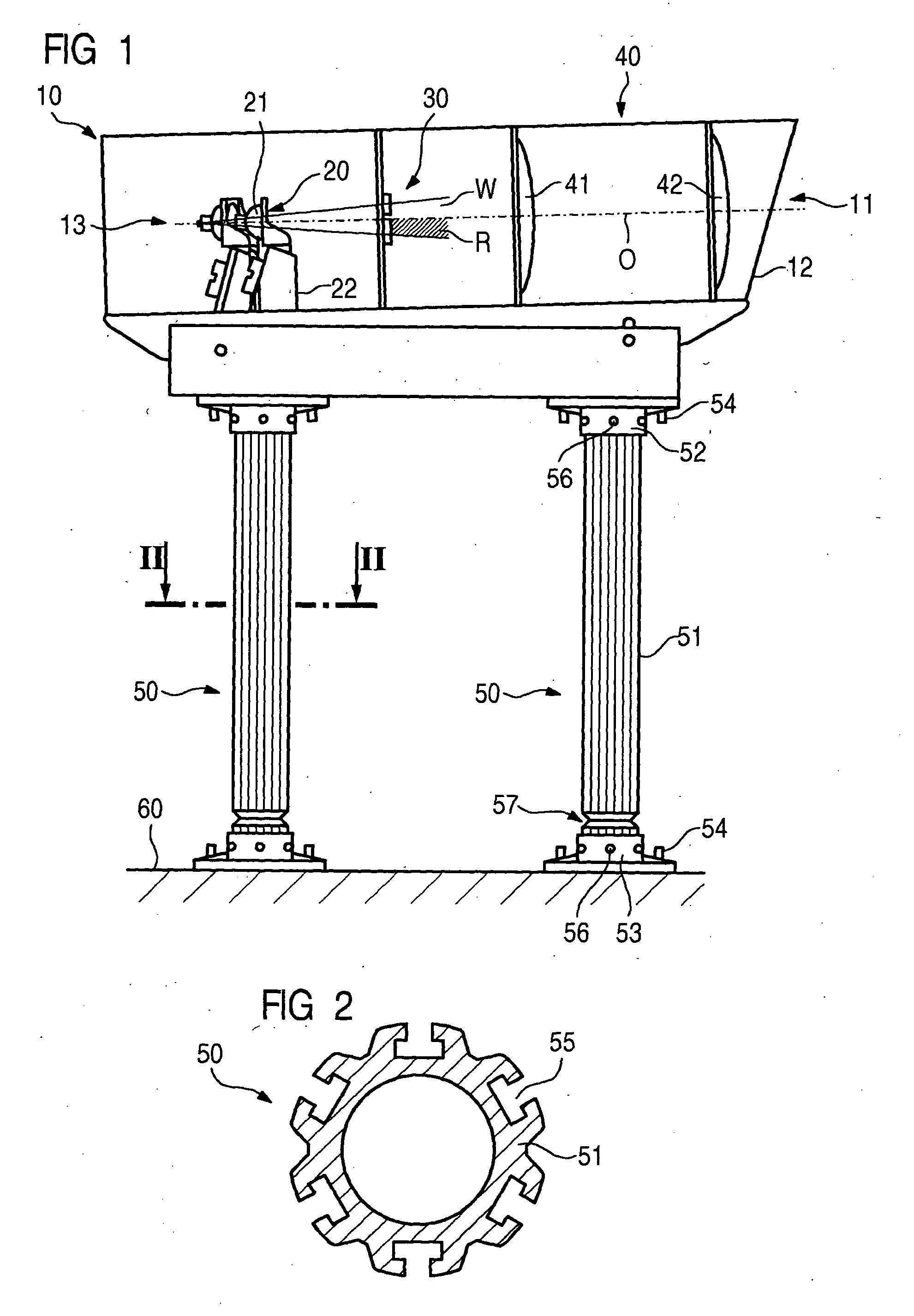
Figure 2 
Figure 3
Abstract
Description
CROSS REFERENCE TO RELATED APPLICATIONS
[0001] This application is the US National Stage of International Application No. PCT / EP2006 / 067178, filed Oct. 9, 2006 and claims the benefit thereof. The International Application claims the benefits of German application No. 10 2005 048 908.7 filed Oct. 10, 2005, both of the applications are incorporated by reference herein in their entirety.FIELD OF INVENTION
[0002] The invention relates to a glide-angle light for approach guidance of aircraft, as claimed in the claims.BACKGROUND OF THE INVENTION
[0003] The final approach of aircraft to an airfield is assisted with the aid of instrument landing systems. This is achieved on the one hand by means of narrow-beam radio guidance beams, which are emitted from radio beacons and allow monitoring of whether an aircraft is on a horizontal and vertical glidepath with respect to the landing runway. On the other hand, visual approach glide-angle indicators provide the pilot with information allowing him to c...
Examples
Embodiment Construction
[0026]As shown in FIG. 1 and FIG. 3, a glide-angle light according to the invention for approach guidance for aircraft comprises a housing 10 which is formed from folded sheet aluminum and has a base wall, two side walls, a rear wall and a removable cover. The front face of the housing 10 is in the form of a light outlet opening 11 and is closed by a front glass 12. According to the invention, only a single light channel 13 extends along an optical axis O in the housing 10. A light source 20, a colored filter 30 and a lens arrangement 40 are arranged one behind the other along the optical axis O. A grouping of three halogen lamps, symmetrically with respect to the optical axis O, is used as the light source 20, producing a white light beam which is directed at the colored filter 30. The colored filter 30 is preferably arranged in combination with a slotted aperture in such a way that the light beam is split into a filtered beam component R and an unfiltered beam component W. The par...