
Roller bearing retainer and needle roller bearing
a technology of roller bearing and retainer, which is applied in the direction of roller bearings, rotary machine parts, mechanical equipment, etc., can solve the problems of difficult to prevent the roller from dropping out, the play amount of the roller cannot be sufficiently provided, and the retainer of the roller could be easily damaged, so as to improve the oil lubrication property in a radial direction, reduce the contact surface pressure at the contact part, and prevent abrasion and burning at the wall surface
Patent Information
- Authority / Receiving Office
- US · United States
- Patent Type
- Applications(United States)
- Current Assignee / Owner
- Publication Date
- 2010-11-04
Smart Images
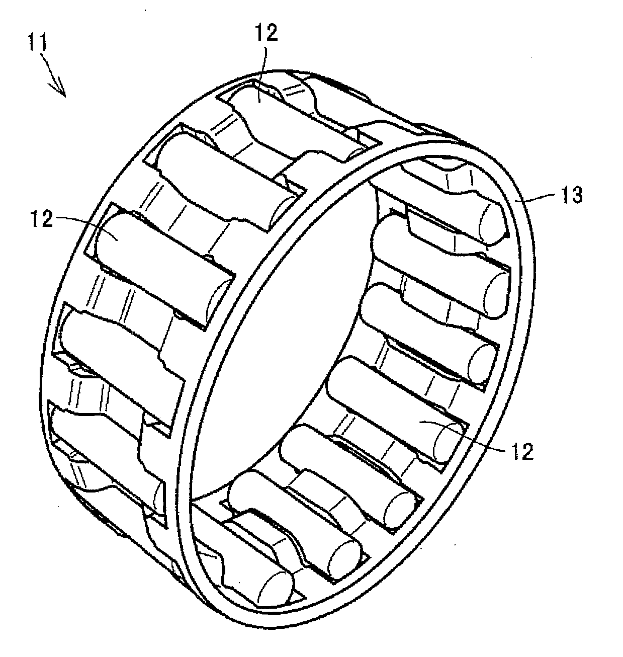
Figure 1 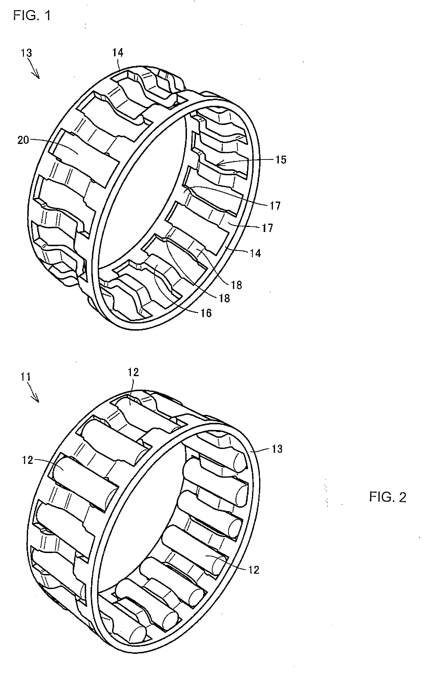
Figure 2 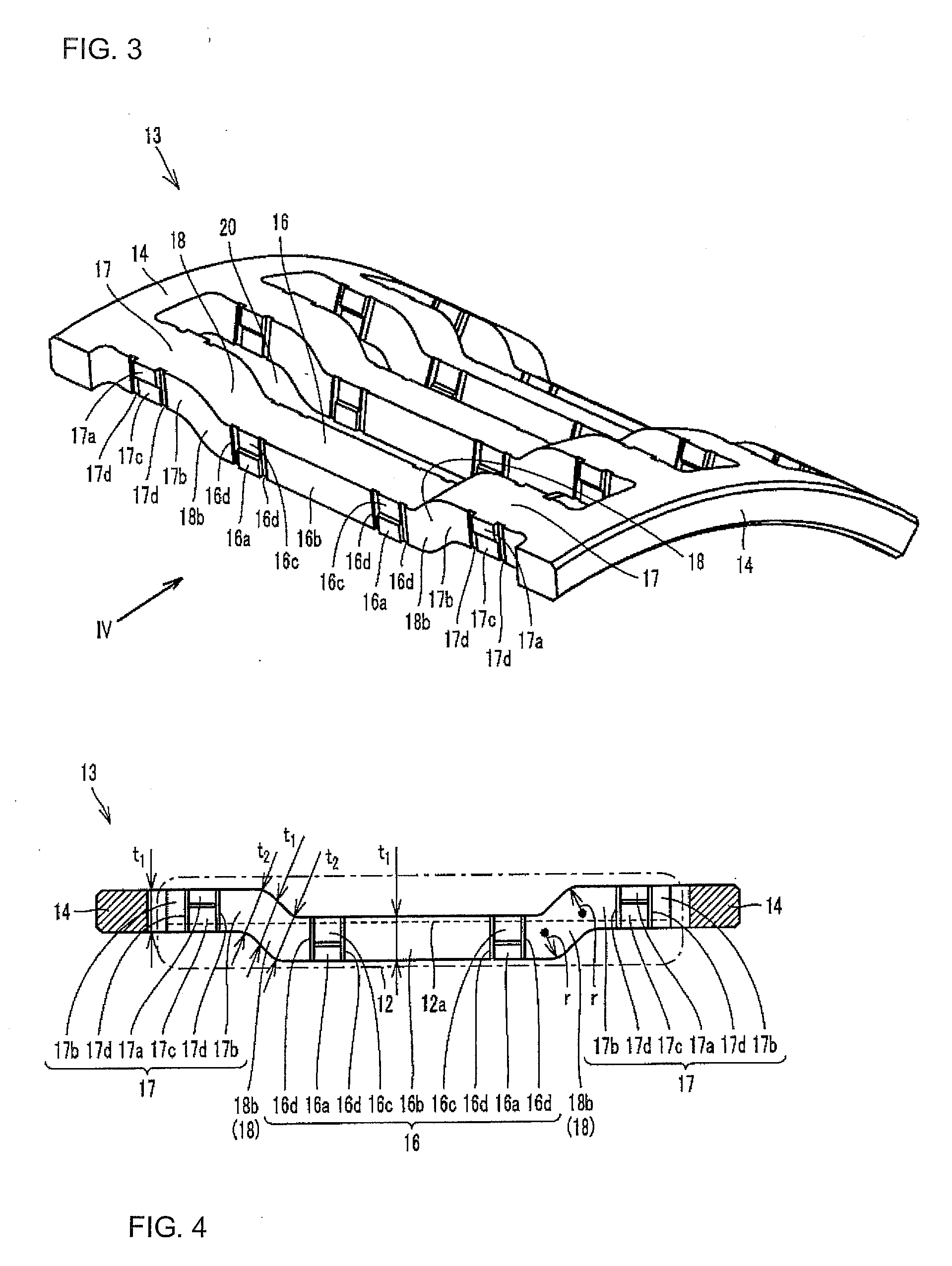
Figure 3
Abstract
Description
TECTHICAL FIELD
[0001] The present invention relates to a roller bearing retainer produced by a pressing process, and a needle roller bearing including the roller bearing retainer.BACKGROUND ART
[0002] A cage & roller type of needle roller bearing composed of rollers and a retainer is employed as an idler bearing of a car transmission, and a bearing for a connecting rod large end of a motorcycle engine in many cases. Such bearing is disclosed in Japanese Unexamined Patent Publication No. 2000-257638 (Patent Document 1), for example.
[0003] According to this document, a pipe-shaped material is formed into an annular member having an M-shaped cross section by a bulging process, and pockets to hold rollers are formed in the annular member, whereby a roller bearing retainer light in weight and large in load capacity can be provided.
[0004] The roller bearing retainer having the above constitution is guided on the outer diameter side in which a column end part and a housing are in contact with e...
Examples
Embodiment Construction
[0079]A description will be made of a needle roller bearing 11 and a roller bearing retainer 13 (referred to as the “retainer 13” simply hereinafter) according to one embodiment of the present invention, with reference to FIGS. 1 to 4. In addition, FIG. 1 is a perspective view showing the retainer 13, FIG. 2 is a perspective view showing the needle roller bearing 11, FIG. 3 is a perspective view showing a configuration of a column part 15 of the retainer 13, and FIG. 4 is a sectional view taken from a direction of an arrow IV in FIG. 3.
[0080]First, referring to FIG. 2, the needle roller bearing 11 includes a plurality of needle rollers 12, and the retainer 13 retaining the plurality of needle rollers 12. Next, referring to FIG. 1, the retainer 13 includes a pair of annular ring parts 14, and the plurality of column parts 15 connecting the pair of ring parts 14 to each other. In addition, a pocket 20 to hold the needle roller 12 is formed between the adjacent column parts 15.
[0081]In...