
Pressure Regulation Control Assembly; Crankcase Ventilation Filter Assembly Including Pressure Regulation Control Assembly; Components; and, Methods
a technology of control assembly and pressure regulator, which is applied in the direction of machine/engine, auxillary pretreatment, separation process, etc., can solve the problem of carrying substantial amounts of fine particulate contaminants
Patent Information
- Authority / Receiving Office
- US · United States
- Patent Type
- Applications(United States)
- Current Assignee / Owner
- Publication Date
- 2011-02-03
Smart Images
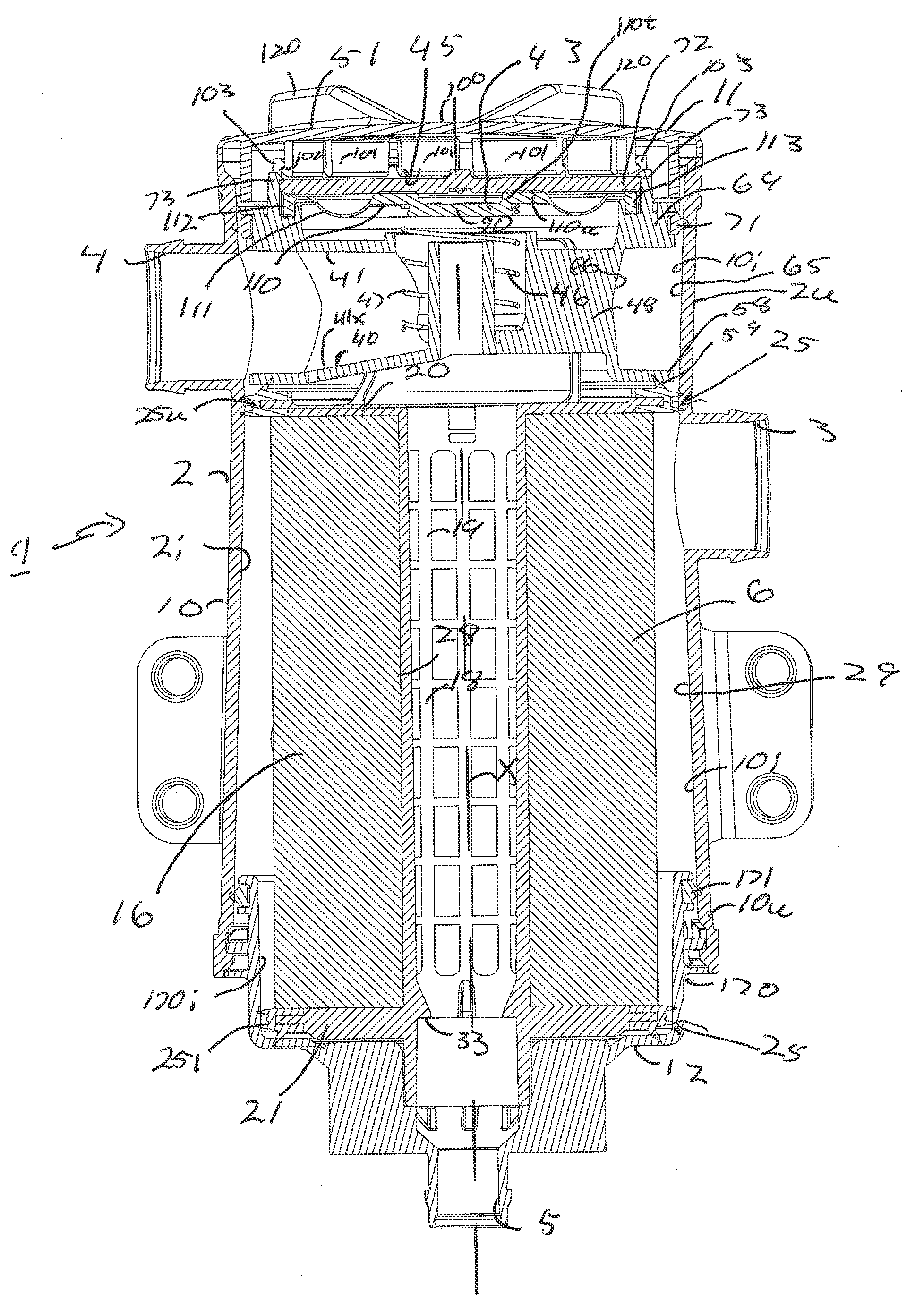
Figure 1 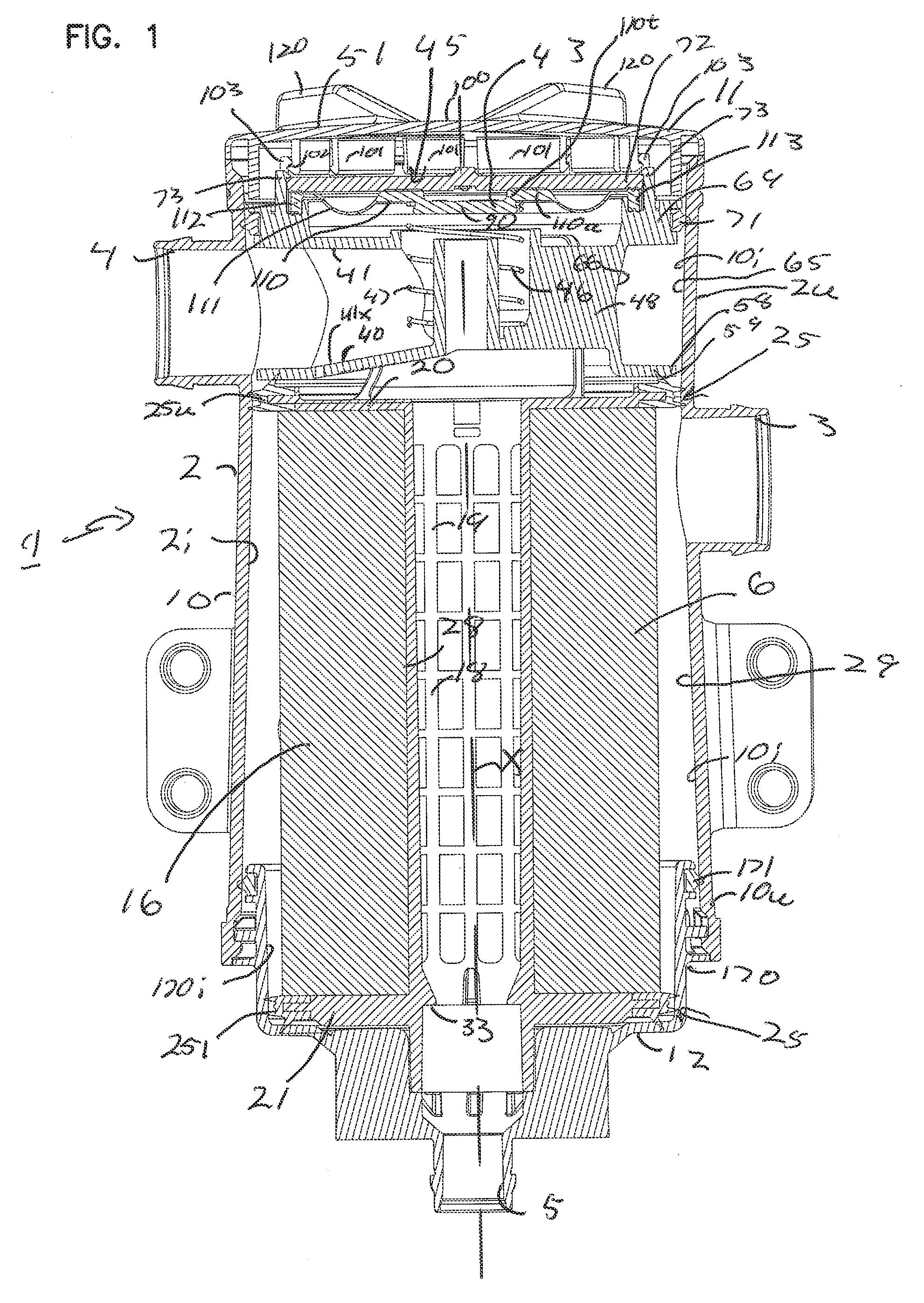
Figure 2 
Figure 3
Abstract
Description
CROSS-REFERENCE
[0001] The present application includes the disclosure of U.S. Provisional Application Ser. No. 61 / 270,408, filed Jul. 7, 2009; the complete disclosure of U.S. 61 / 270,408 being incorporated herein by reference.
[0002] A claim of priority is made to U.S. Provisional Application Ser. No. 61 / 270,408; to the extent appropriate.FIELD OF THE DISCLOSURE
[0003] The disclosure particularly concerns a pressure regulator (or regulation) valve arrangement or assembly (i.e., a pressure control valve) usable in filter systems, and related methods. The pressure regulator valve assembly provides for preferred pressure control by using multiple stages or phases of operation.
[0004] In an example application, this disclosure relates to systems and methods for separating hydrophobic fluids (such as oils) which are entrained as an aerosol, from gas streams (for example, air streams). Further, arrangements provide for filtration of other contaminants such as carbon material, from the gas stream....
Examples
Embodiment Construction
I. The Example Assembly of FIGS. 1-7
[0029]A. General Operation, FIG. 1
[0030]Reference numeral 1, FIG. 1, generally discloses a crankcase ventilation filter assembly or arrangement according to the present disclosure. The crankcase ventilation filter assembly 1 includes a housing 2 having a gas flow inlet arrangement 3 and a gas flow outlet arrangement 4. The housing 2 further includes a (lower) liquid drain outlet arrangement 5.
[0031]In operation, crankcase gases, i.e., engine blow by gases, are directed into gas flow inlet arrangement 3. The gases contain, entrained therein, particulate contaminant and entrained liquid. Within an interior 2i of the housing 2, the gases are directed through a filter cartridge 6, as the gases pass (in normal flow) from the gas flow inlet arrangement 3 to the gas flow outlet arrangement 4. Within the filter cartridge 6, at least a portion of liquid entrained within the gases is coalesced and drained to the lower drain outlet arrangement 5 and outwardl...