
Engagement structure between a mouth member of a pressure vessel and a blow pin, mouth member structure of a pressure vessel having the engagement structure and method of making a pressure vessel
a technology of engagement structure and pressure vessel, which is applied in the direction of vessel construction details, mechanical devices, other domestic objects, etc., can solve the problems of cracks in the bonding interface, the state of bonding between the coating and the blow pin cannot be easily prevented, and the bonding strength reduction
Patent Information
- Authority / Receiving Office
- US · United States
- Patent Type
- Applications(United States)
- Current Assignee / Owner
- Publication Date
- 2013-02-28
Smart Images
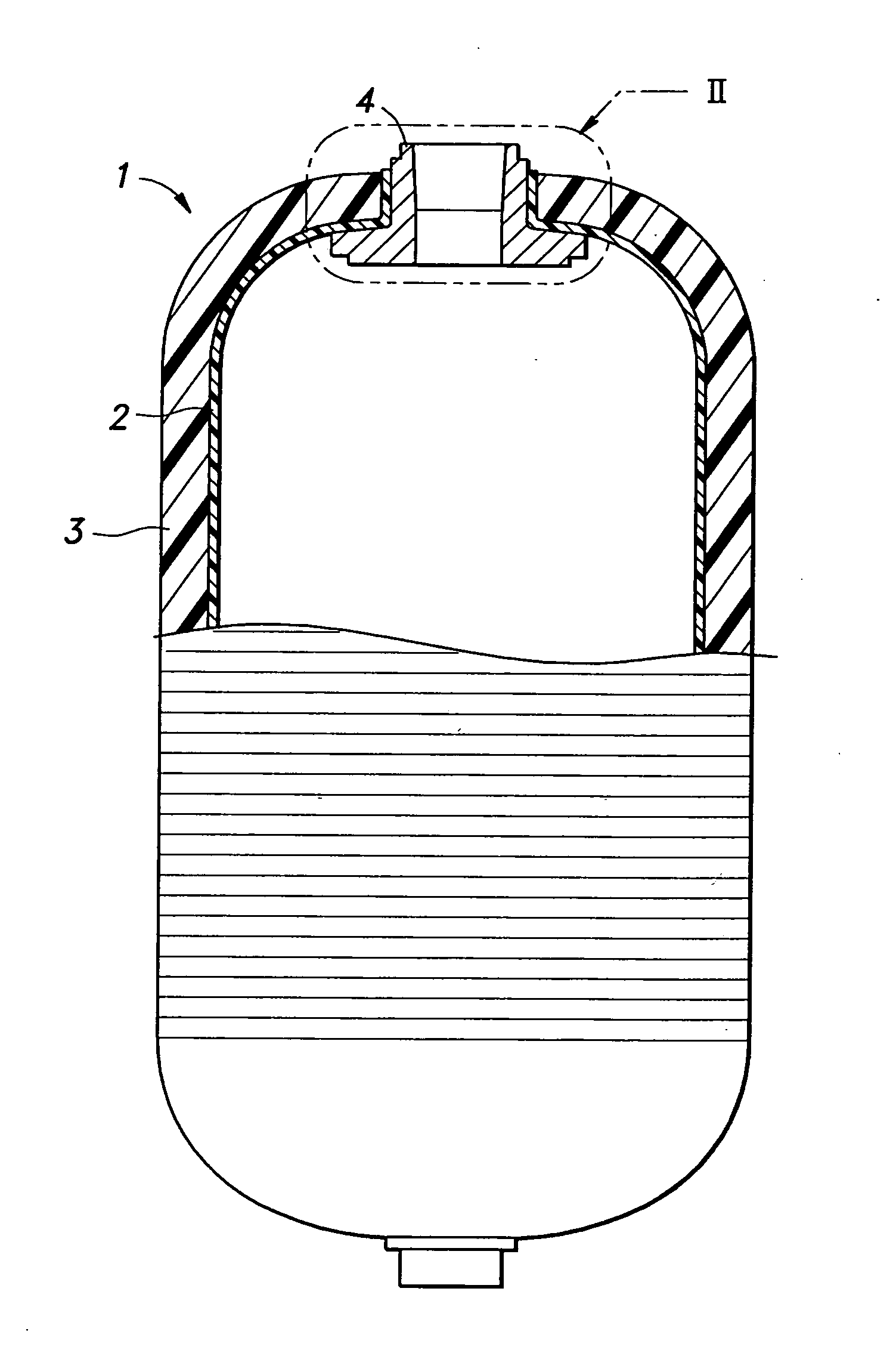
Figure 1 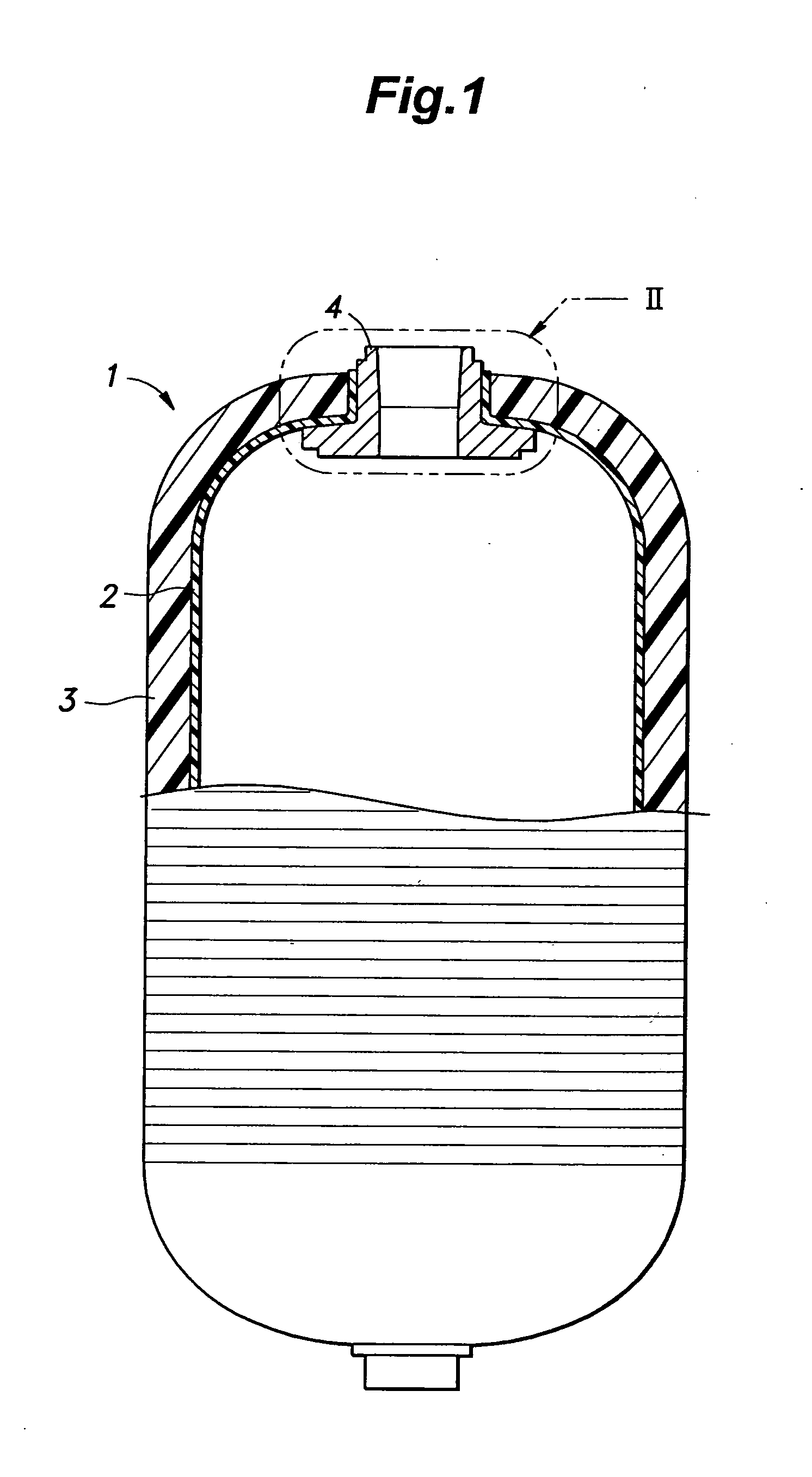
Figure 2 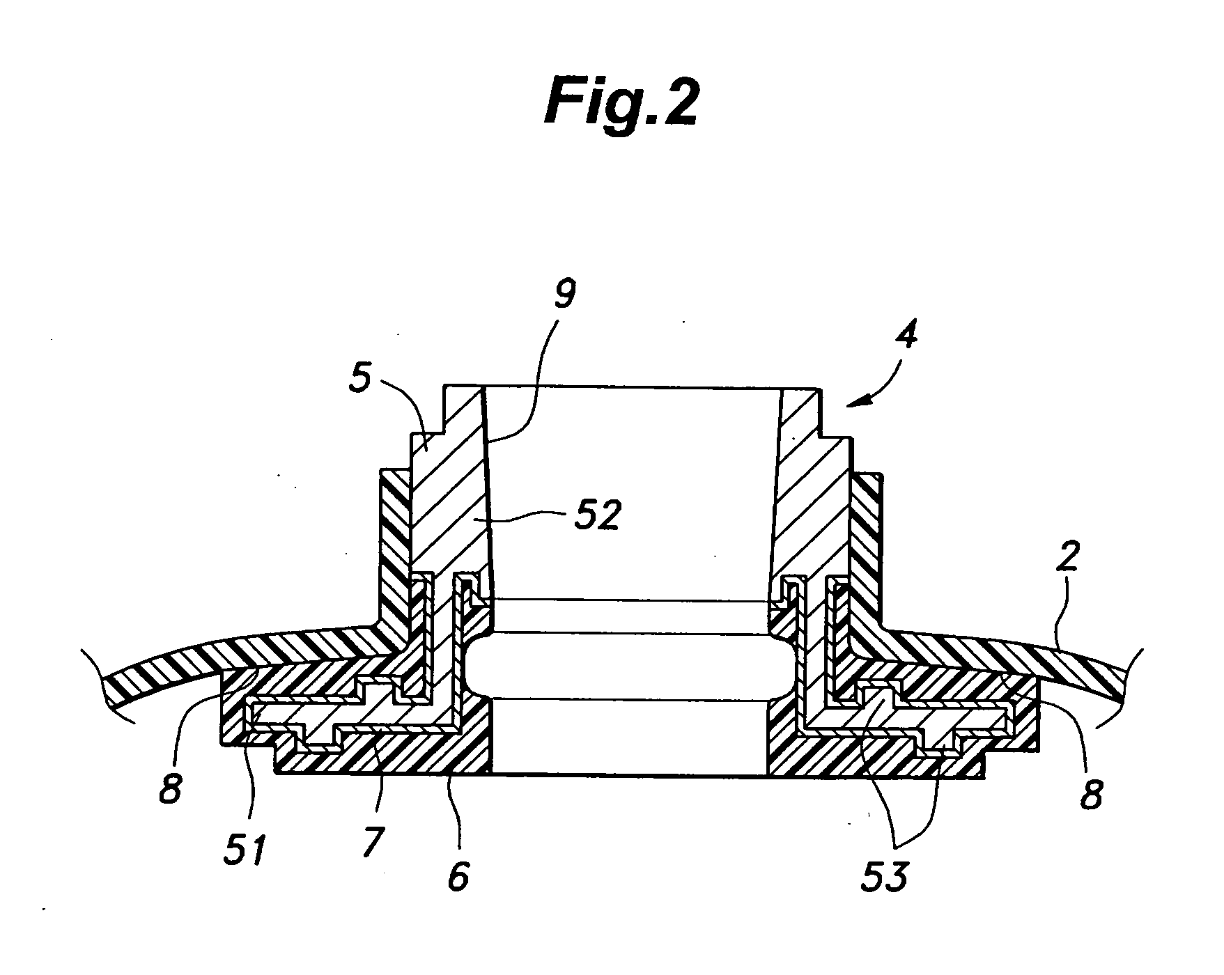
Figure 3
Abstract
Description
TECHNICAL FIELD
[0001] The present invention relates to an engagement structure between a mouth member of a pressure vessel for storing compressed gas such as liquefied petroleum gas (LPG) and a blow pin, and a seal structure for such a pressure vessel.BACKGROUND OF THE INVENTION
[0002] LPG contributes to the prevention of acid rain because of a low sulfur content thereof, and the burned gas contains a relatively small amount of CO2 as compared with petroleum and coal. Therefore, LNG is considered as an ecological, clean energy source. LNG can be liquefied under a relatively low pressure, and the liquefied volume thereof is a 250th of the original gas volume. Furthermore, LNG can be stored and transported in a tank which is capable of withstanding a relatively low pressure. Currently, steel pressure vessels are commonly used for storing and transporting LNG in Japan, but light weight pressure vessels made of composite materials based on plastic technology are widely used in western coun...
Examples
Embodiment Construction
[0030]An example of a pressure vessel 1 to which the present invention is applied is described, and, then, an engagement structure between a mouth member 4 of the pressure vessel 1 and a blow pin 11, a mouth member structure of the pressure vessel 1 and a manufacturing method of the pressure vessel are described in the following. Referring to FIG. 1, the pressure vessel 1 comprises a plastic liner 2 for receiving primarily gas or liquid therein, a fiber reinforced plastic layer 3 reinforcing the outer surface of the plastic liner 2 and a mouth member 4 projecting out of the plastic liner 2 and the fiber reinforced plastic layer 3 for introducing and expelling air or gas into and out of the pressure vessel 1. The detailed bonding structure between the plastic liner 2 and the mouth member 4 is omitted in FIG. 1, and will be described in more detail hereinafter.
[0031]The plastic liner 2 constitutes a vessel for receiving gas or liquid, and can be made of material that suits the content...