
Optical pickup
a pickup and optical technology, applied in the field of optical pickups, can solve problems such as mismatching between, and achieve the effect of stable tracking control
Patent Information
- Authority / Receiving Office
- US · United States
- Patent Type
- Applications(United States)
- Current Assignee / Owner
- Publication Date
- 2011-07-28
- Estimated Expiration
- Not applicable · inactive patent
Smart Images
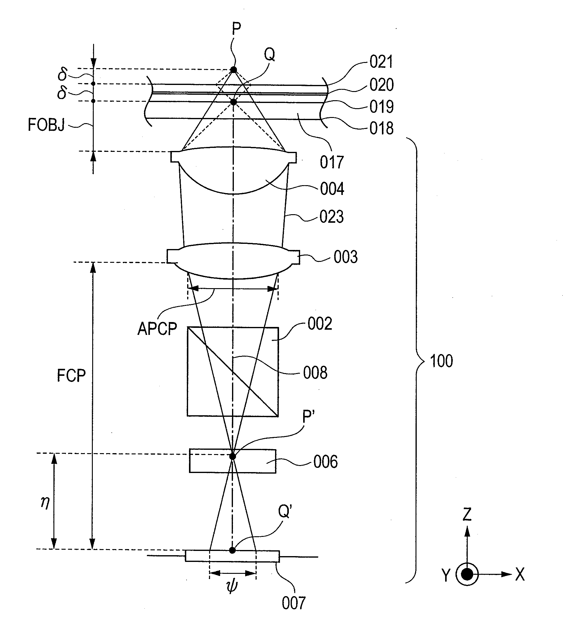
Figure 1 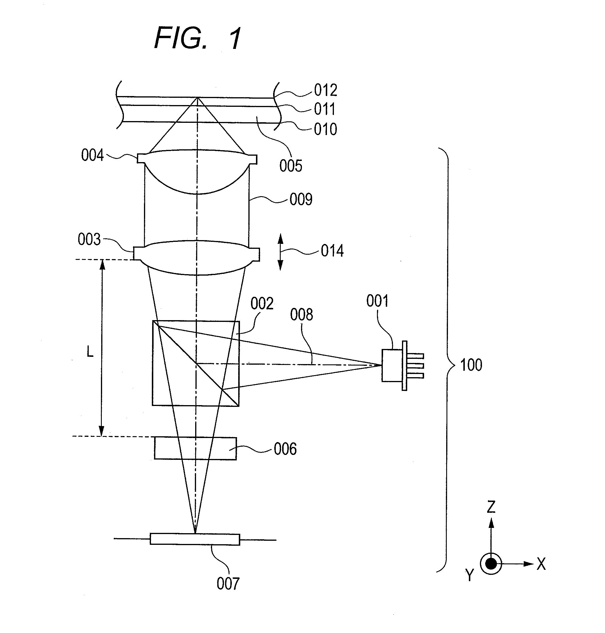
Figure 2 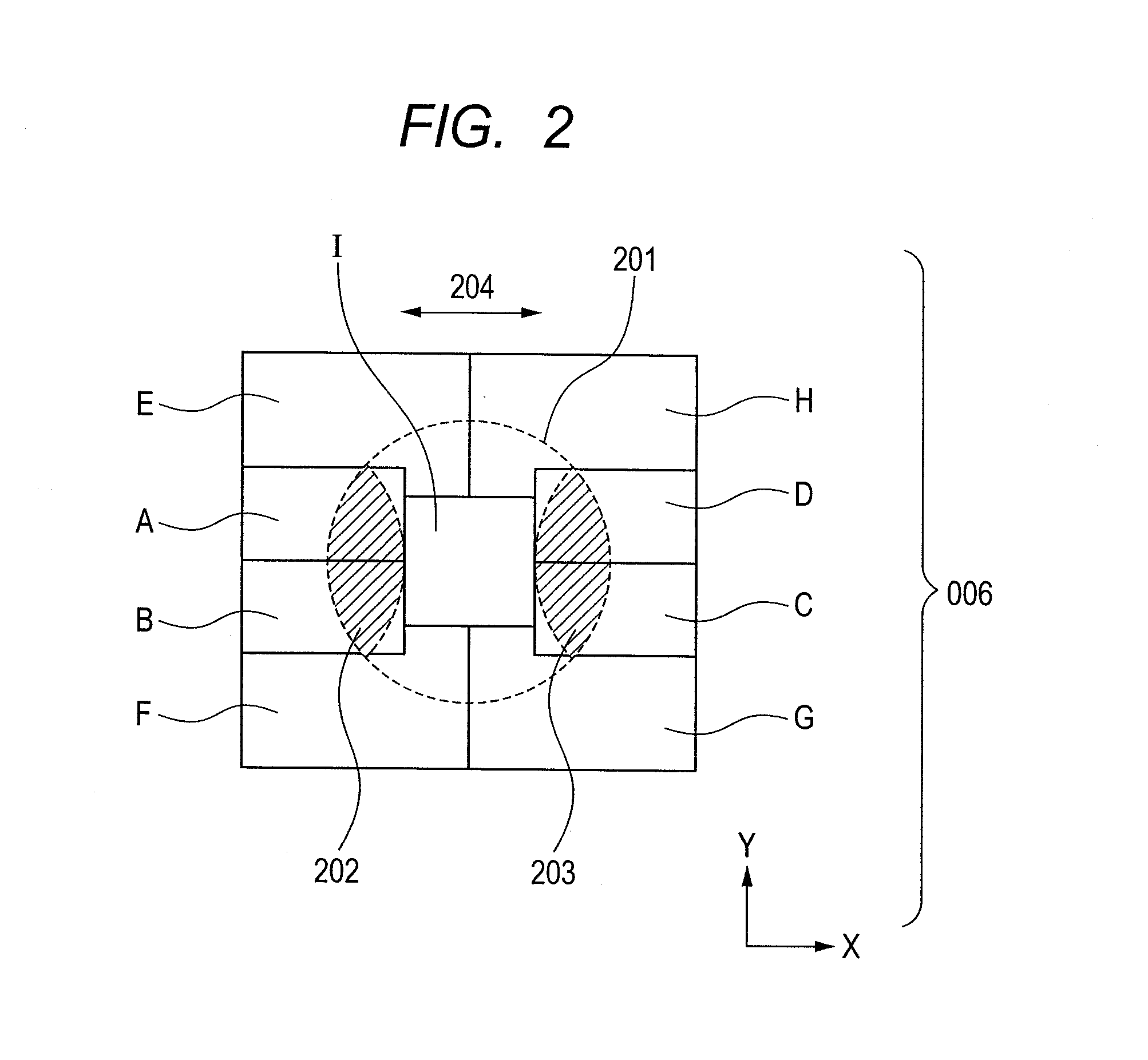
Figure 3
Abstract
Description
CLAIM OF PRIORITY
[0001] The present application claims priority from Japanese patent application serial No JP 2010-012753, filed on Jan. 25, 2010, the content of which is hereby incorporated by reference into this application.BACKGROUND OF THE INVENTION
[0002] (1) Field of the Invention
[0003] The present invention relates to an optical pickup that records information on or reproduces information from optical discs.
[0004] (2) Description of the Related Art
[0005] A technique concerned with the present invention is described in Japanese laid-open patent application publication No. JP-A-2004-281026 that discloses an optical pickup.SUMMARY OF THE INVENTION
[0006] Optical discs are one of the media drawing a great deal of attention as long-storage media in terms of cost reduction, the reliability of data storage, and the like. Optical discs with two information layers, such as digital versatile discs (DVDs) and Blu-ray discs (BDs), have heretofore been standardized for increased capacity. Current...
Examples
first embodiment
[0029]An optical pickup according to a first embodiment of the present invention is described in detail below. An optical pickup adapted for recording information on or reproducing information from a double-layered disc of current Blu-ray disc (BD) standards is described first. FIG. 1 is a schematic diagram showing a configuration of the optical pickup 100 according to the first embodiment. In the figure, the X-direction is equivalent to the radial direction of the optical disc, the Z-direction to the vertical direction thereof, and the Y-direction to the direction parallel to tracks of the optical disc.
[0030]An optical beam is emitted as divergent light from a light source 001. Recording information on or reproducing information from a BD generally uses a semiconductor laser that emits optical beams of 405±10 nm in wavelength. The present embodiment assumes that the light source 001 emits optical beams of 405±10 nm in wavelength. A dotted-and-dashed line 008 denotes a central optic...
second embodiment
[0115]A modification in the optical pickup of the first embodiment is described below as a second embodiment. The optical pickup of the second embodiment, a modification in the optical pickup 100 of the first embodiment, differs from the optical pickup 100 of the first embodiment in terms of region layout in a diffraction grating and photo-receiver layout in a detector. The present embodiment, as with the first embodiment, envisages information reproduction from a double-layered disc having a 25-μm space between two information layers.
[0116]FIG. 8 shows the diffraction grating 015 of the second embodiment, as viewed from the detector side. The diffraction grating 015 includes a region AB, which is equivalent to a region formed by combining the regions A and B of the diffraction grating 006. The diffraction grating 015 also includes a region CD, which is equivalent to a region likewise formed by combining the regions C and D of the diffraction grating 006. The regions AB and CD of th...
third embodiment
[0141]Using the optical pickup of the first embodiment to reproduce information from a triple-layered optical disc having three information layers is described as a third embodiment. Standards specify that double-layered discs should have a 25-μm space between the two information layers. The present embodiment envisages a triple-layered disc formed by adding a third information layer to a surface side of a double-layered disc, with the same space of 25 μm as that of double-layered discs,
[0142]In the present embodiment, the triple-layered disc is denoted as 017, an information layer located nearest to the surface of the triple-layered disc, as 019, an intermediate information layer as 020, and an information layer located farthest from the surface, as 021. Interlayer tolerances for the three information layers are ±5 μm, the same tolerances as defined in double-layered disc standards. The space between the information layer 019 nearest the surface, and the information layer 021 farth...