
Personal watercraft
Patent Information
- Authority / Receiving Office
- US · United States
- Current Assignee / Owner
- Publication Date
- 2011-10-13
Smart Images
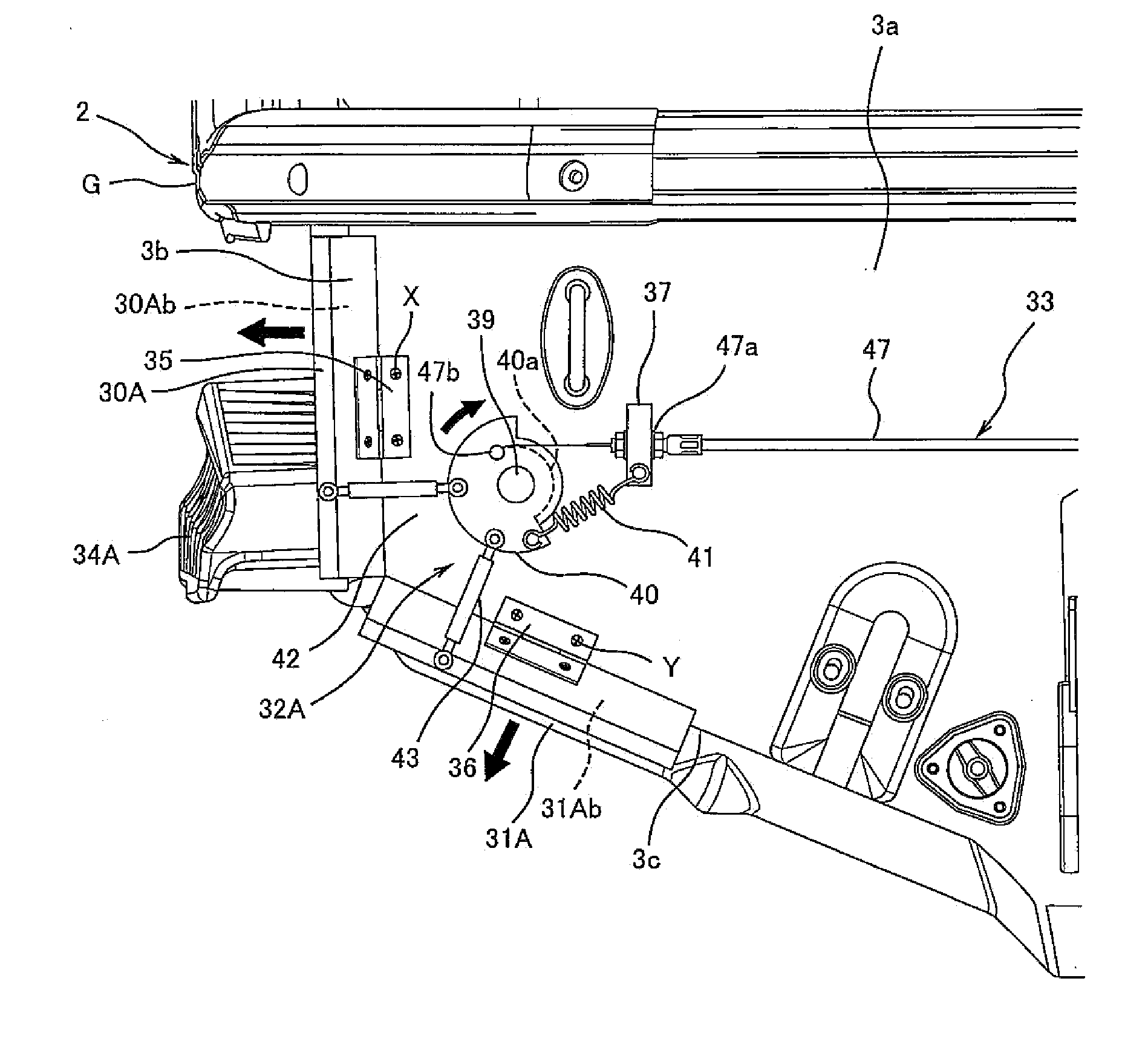
Figure 1 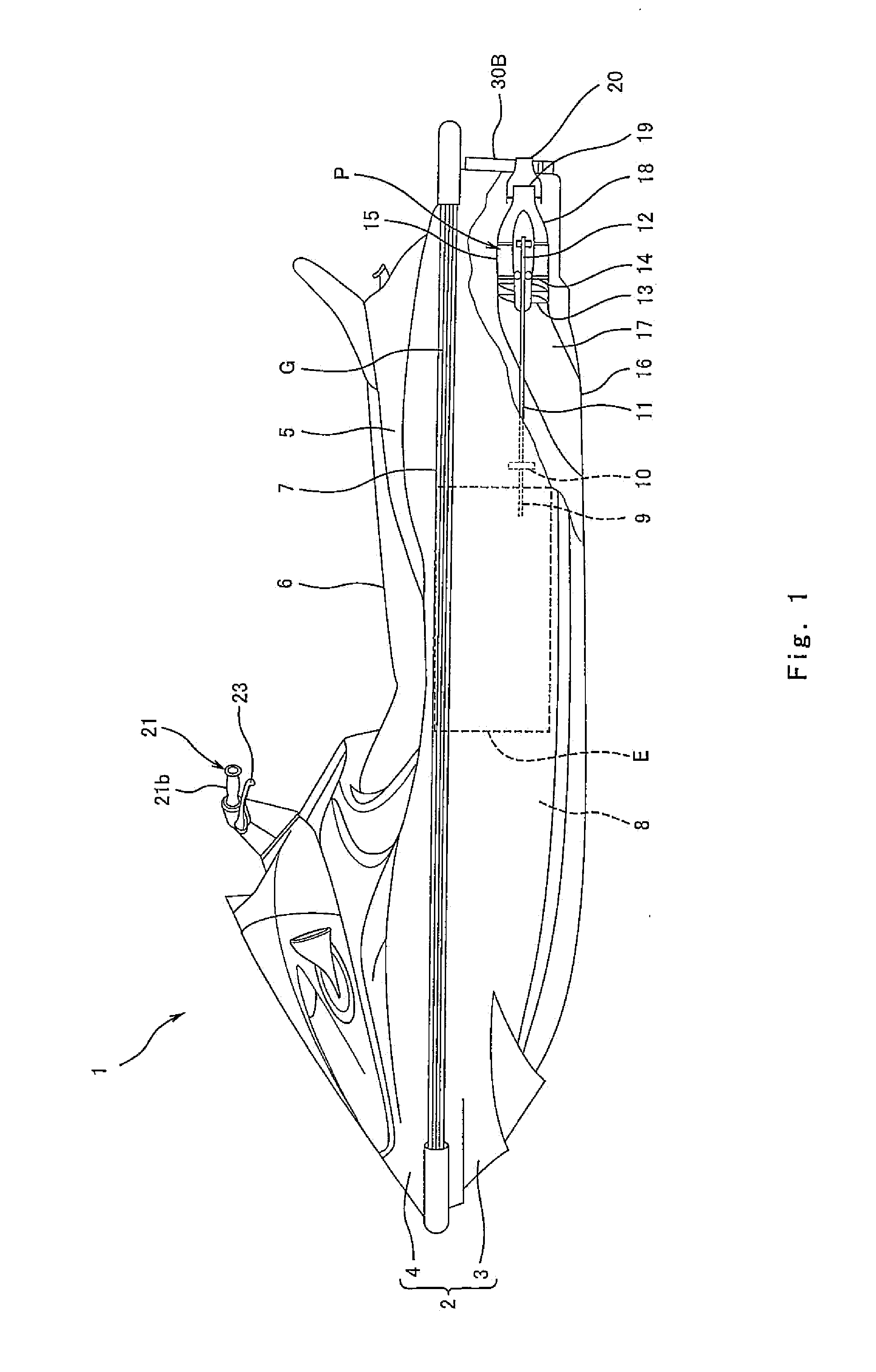
Figure 2 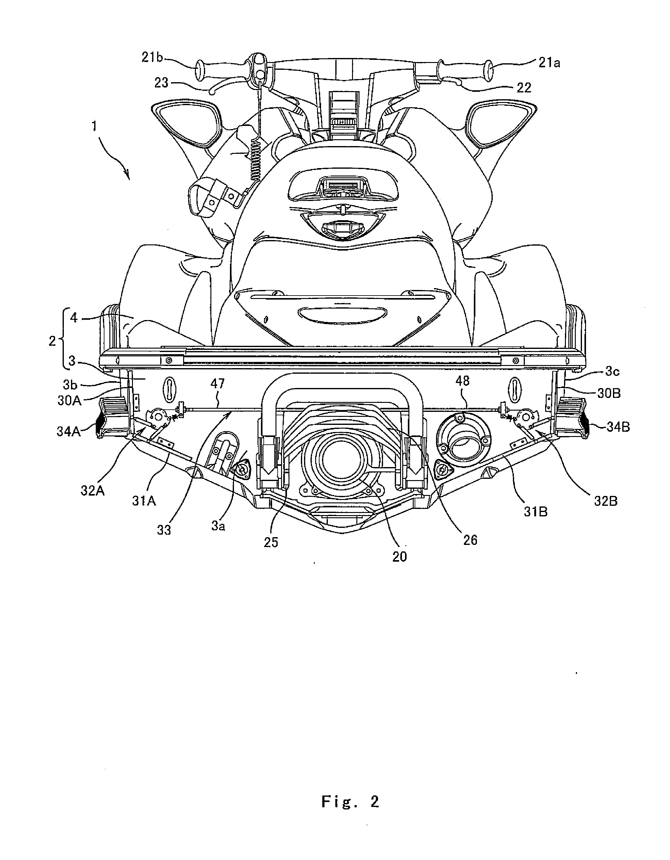
Figure 3
Abstract
Description
BACKGROUND OF THE INVENTION
[0001] 1. Field of the Invention
[0002] The present invention relates to a personal watercraft (PWC) which is configured to eject water rearward from a body thereof to generate a propulsive force.
[0003] 2. Description of the Related Art
[0004] A personal watercraft is configured to be decelerated by water resistance applied to a body thereof. It is desired that the personal watercraft be decelerated with a high responsiveness to a rider's operation of moving a throttle lever to a closed position. If the body of the watercraft is designed to increase the water resistance applied to the body, its acceleration capability and fuel efficiency decrease.
[0005] U.S. Pat. No. 6,691,634 and U.S. Pat. No. 7,007,621 disclose a technique in which a resistive element protrudes downward from a hull bottom as desired at the rear portion of a body to allow the body to be decelerated by the water resistance. If the water resistance applied to the resistive element protruding downw...
Examples
Embodiment Construction
[0017]Hereinafter, an embodiment of the present invention will be described with reference to the drawings. As used herein, the stated directions refer to directions from the perspective of a rider straddling a watercraft, unless otherwise explicitly noted.
[0018]FIG. 1 is a left side view of personal watercraft 1 according to an embodiment of the present invention. As shown in FIG. 1, the watercraft 1 includes a body 2 including a hull 3 and a deck 4 covering the hull 3 from above. The hull 3 and the deck 4 are connected to each other by a gunnel line section G which protrudes horizontally outward from the body 2. A center region in a width direction of the rear portion of the deck 4 protrudes upward to form a protruding portion 5. A seat 6 is mounted over the upper surface of the protruding portion 5. A deck floor 7 is provided on opposite (right and left) sides in the width direction of the protruding portion 5. The deck floor 7 is lower than the protruding portion 5 and is substa...