
Generator in particular for a wind turbine
Patent Information
- Authority / Receiving Office
- US · United States
- Current Assignee / Owner
- Publication Date
- 2012-04-19
- Estimated Expiration
- Not applicable · inactive patent
Smart Images
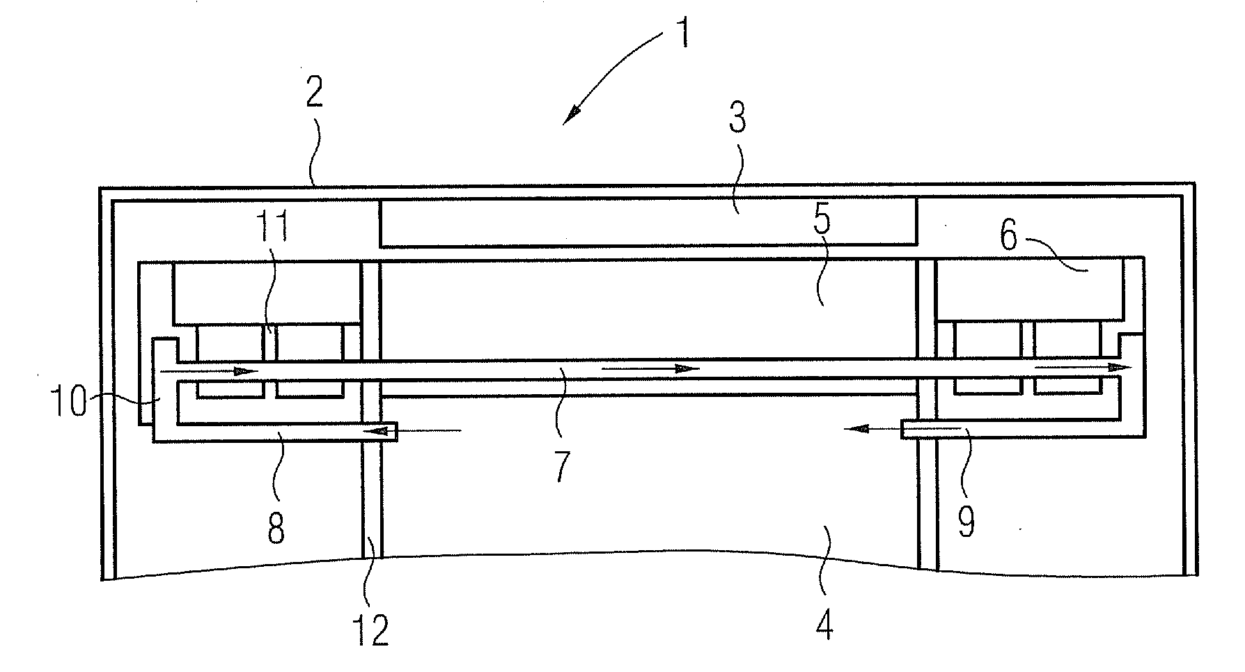
Figure 1 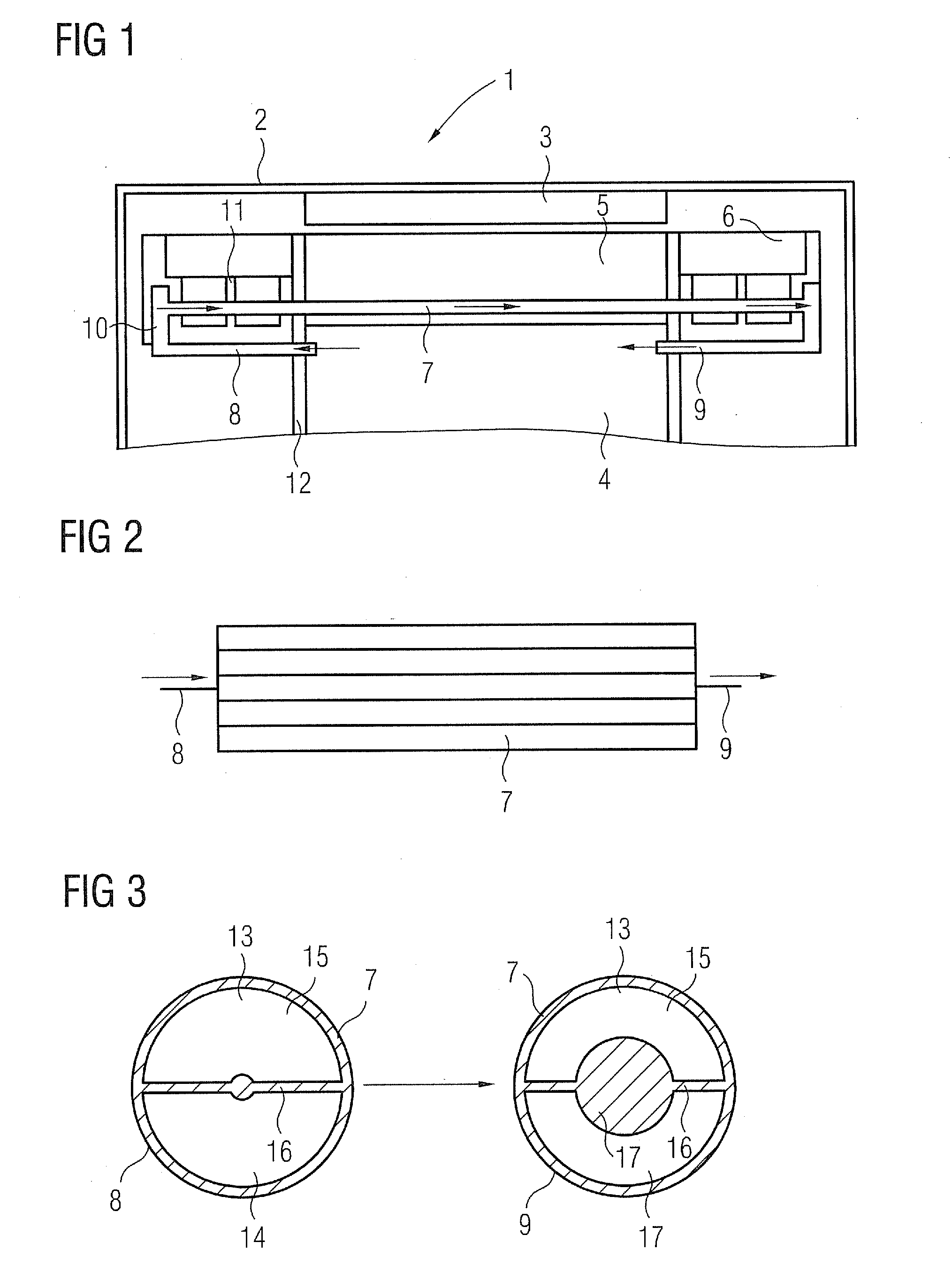
Figure 2
Abstract
Description
CROSS REFERENCE TO RELATED APPLICATIONS
[0001] This application claims priority of European application No. 10187373.5 filed Oct. 13, 2010, which is incorporated by reference herein in its entirety.FIELD OF THE INVENTION
[0002] The present invention relates to a generator, in particular for a wind turbine, comprising a rotor with a number of circumferentially arranged magnets, a stator with lamination and conductors and a means for cooling the stator.BACKGROUND OF THE INVENTION
[0003] Such generators are components of wind turbines, which are provided with a rotor shaft which is part of the electrical generator producing electricity during movement of the rotor relative to the stator. The stator comprises a lamination and conductors, the rotor comprises a number of permanent magnets or electrically charged magnets so that an electric voltage is generated when the rotor is turned.
[0004] In generators heat losses occur, mainly from electromagnetic losses (Joule losses, iron losses, copper lo...
Examples
Embodiment Construction
[0022]FIG. 1 shows a detail of a generator 1 in a cross-sectional view. The generator 1 comprises a rotor 2, comprising a number of magnets 3, arranged in circumferential direction.
[0023]A stator 4 comprises a stator lamination 5 with end windings 6 on both sides of the stator lamination 5.
[0024]When rotor 2, which has a circular shape, is rotated around the stator 4, an electric current is generated in the windings of the stator lamination 5. During movement of the rotor 2 heat losses occur so that the stator lamination 5 is heated up. In order to dissipate the heat a number of cooling pipes 7 are provided within the stator lamination 5. A large number of cooling pipes 7 is arranged in parallel along the circumferential direction of stator 4. In the embodiment of FIG. 1 all cooling pipes 7 are connected parallel, a pump (not shown) is used for conveying a coolant through the cooling pipes 7.
[0025]Each cooling pipe 7 comprises an inlet 8 and an outlet 9 the arrows indicate the flow ...