
Wellbore plug and method
a wellbore and plug technology, applied in the direction of wellbore/well accessories, fluid removal, sealing/packing, etc., can solve the problems of substantially higher setting force, inducing tension and compressive stresses in the mandrel, and affecting the operation of the plug, so as to achieve the effect of eliminating tension stress
Patent Information
- Authority / Receiving Office
- US · United States
- Patent Type
- Applications(United States)
- Current Assignee / Owner
- Publication Date
- 2013-01-10
- Estimated Expiration
- Not applicable · inactive patent
Smart Images
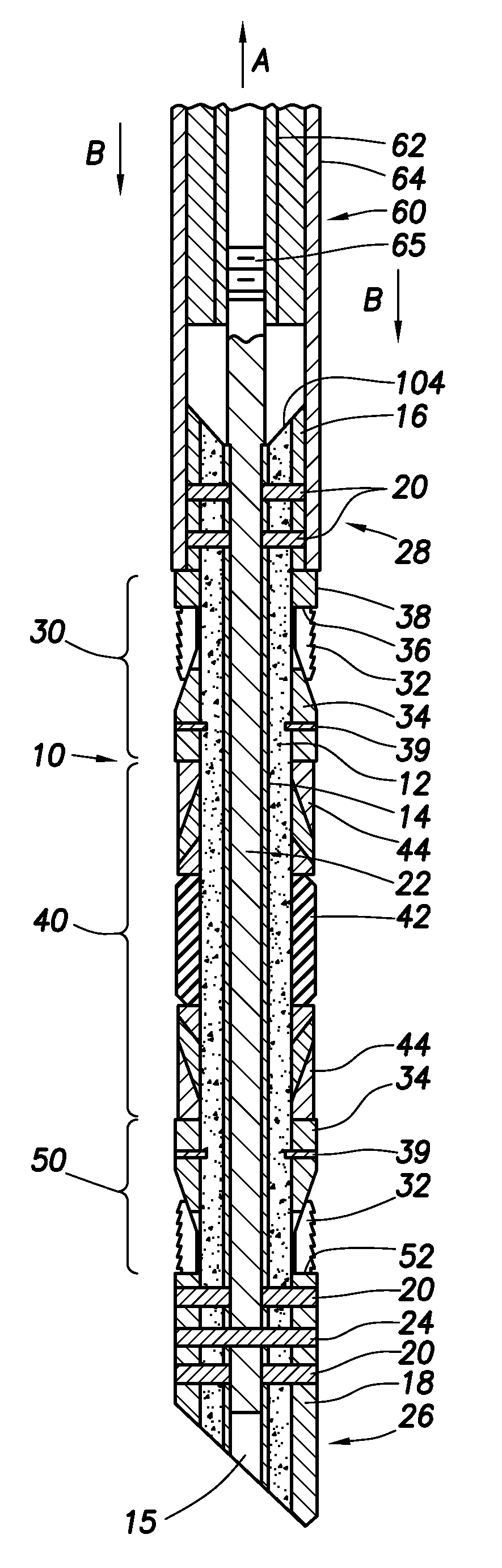
Figure 1 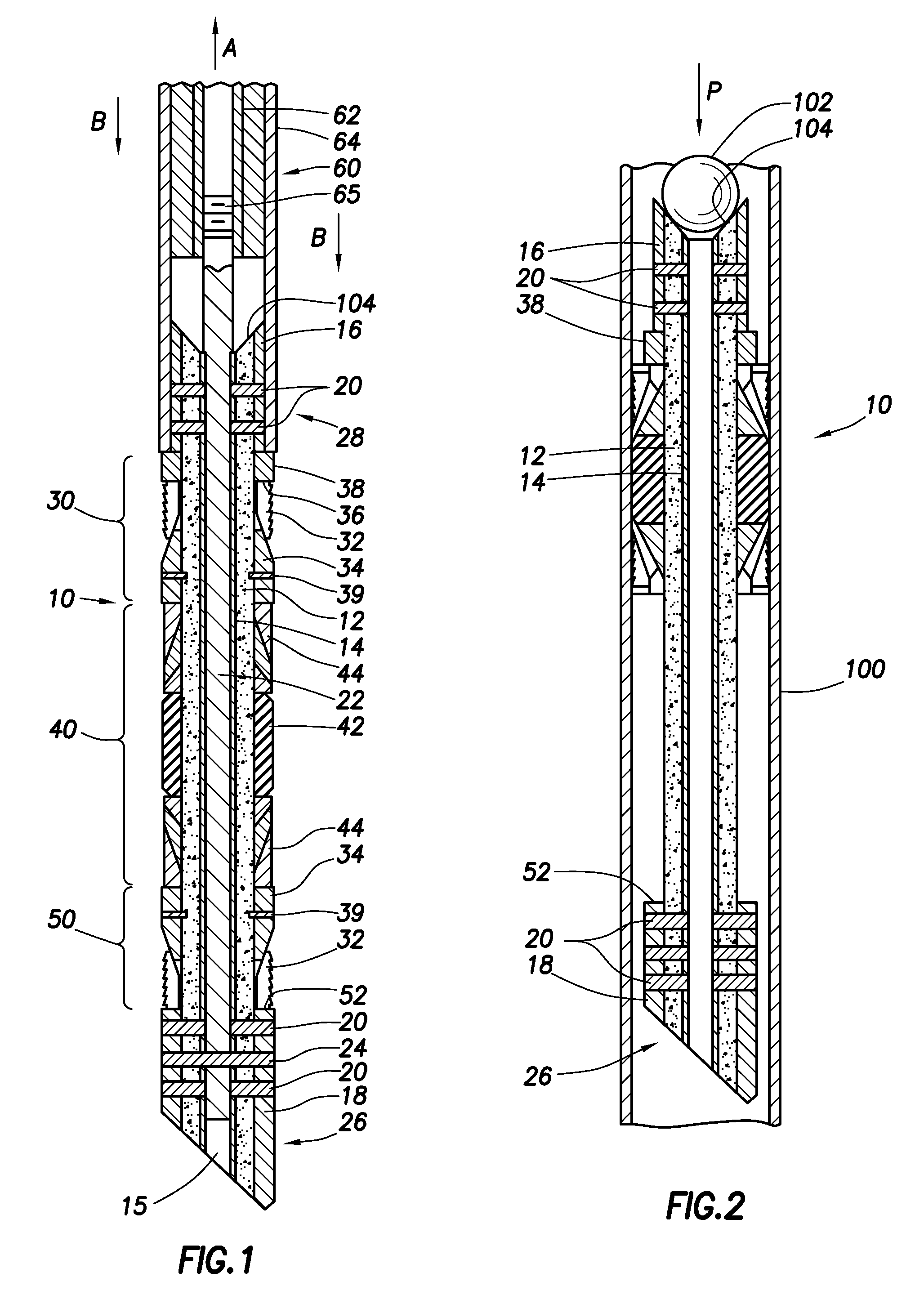
Figure 2 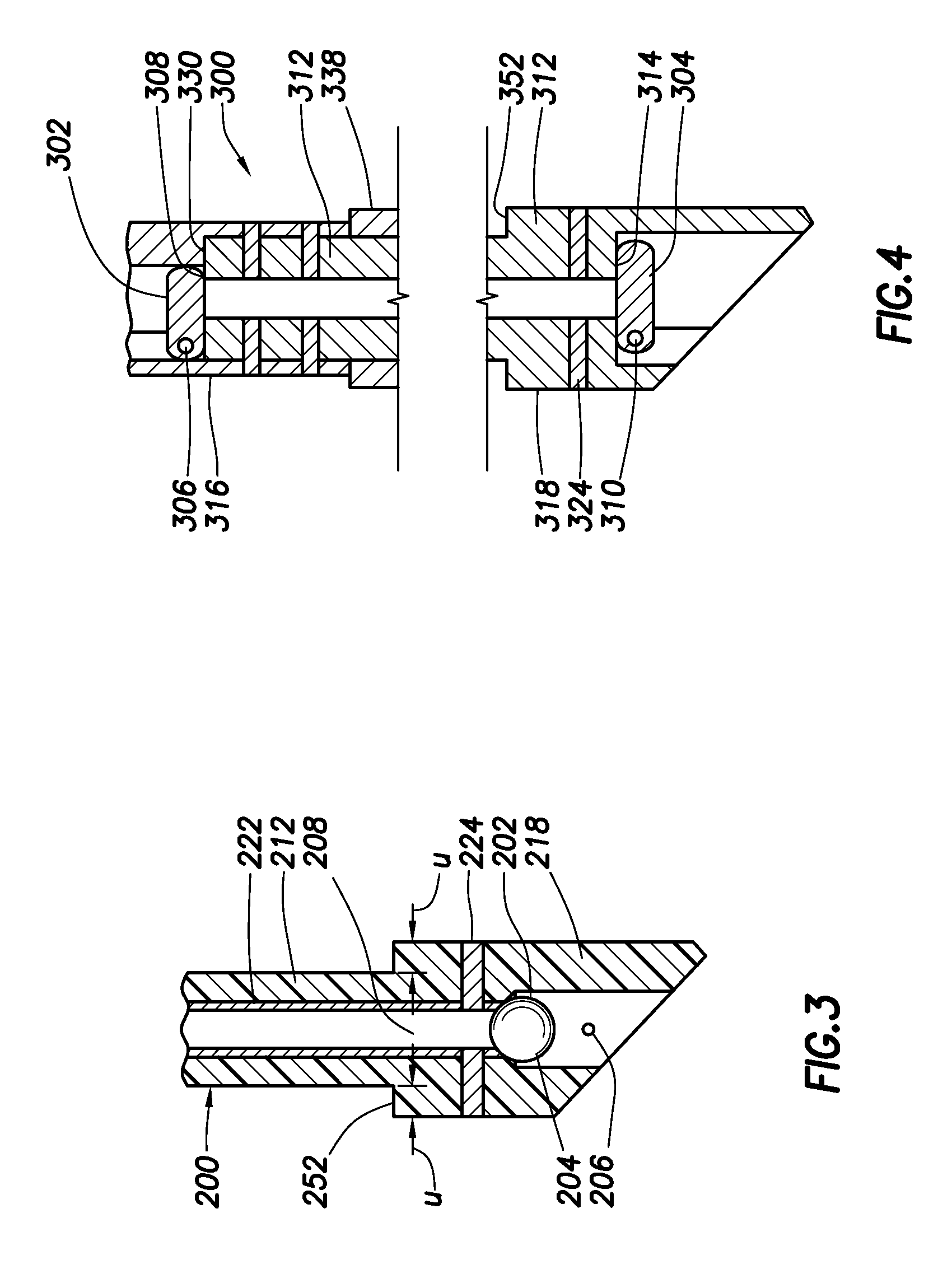
Figure 3
Abstract
Description
CROSS REFERENCE TO RELATED APPLICATIONS
[0001] This application claims priority from U.S. Provisional Patent Application No. 61 / 505,195, filed Jul. 7, 2011, entitled “Wellbore Plug and Method,” which is hereby incorporated by reference in its entity.BACKGROUNDTechnical Field
[0002] These inventions relate generally to methods and apparatus for drilling and completing subterranean wells and, more particularly, drillable wellbore plugs designed to have mandrels made of concrete or other easy-to-drill materials or shapes.
[0003] In the drilling of wells and in mining applications, it is necessary to temporarily isolate sections of a wellbore. For example, a common method sets a plurality of plugs to isolate and successively treat sections of the wellbore. As used herein, the term “plug” is used to refer to bridge plugs, packers, frac plugs, cementing shoes, squeeze plugs and the like utilized at subterranean wellbore locations. This isolation method has been accomplished using “drillable wel...
Examples
Embodiment Construction
[0023]Referring now to the drawings wherein like reference characters designate like or corresponding parts throughout the several views, there is shown in FIG. 1 an embodiment of an improved double-slip type wellbore plug assembly 10 according to the present inventions. The plug embodiment selected for use in describing the present inventions comprises what is known in the industry as a frac plug. As will be described in detail, the frac plug, once set in the wellbore, permits hydrocarbon production flow along the wellbore upward through the plug, while preventing frac fluids pumped into the well to flow in a downward or downhole direction. For purposes of description, plug assembly 10 is illustrated in the figures with the upper end of the plug 28 orientated toward the top of the drawing page and lower end of the plug 26 toward the bottom of the page. It is to be understood that the embodiment selected for use as an example is not intended to limit the inventions to the selected c...