
Direction changing device, medical assembly having the same, and method
Patent Information
- Authority / Receiving Office
- US · United States
- Current Assignee / Owner
- Publication Date
- 2013-08-15
Smart Images
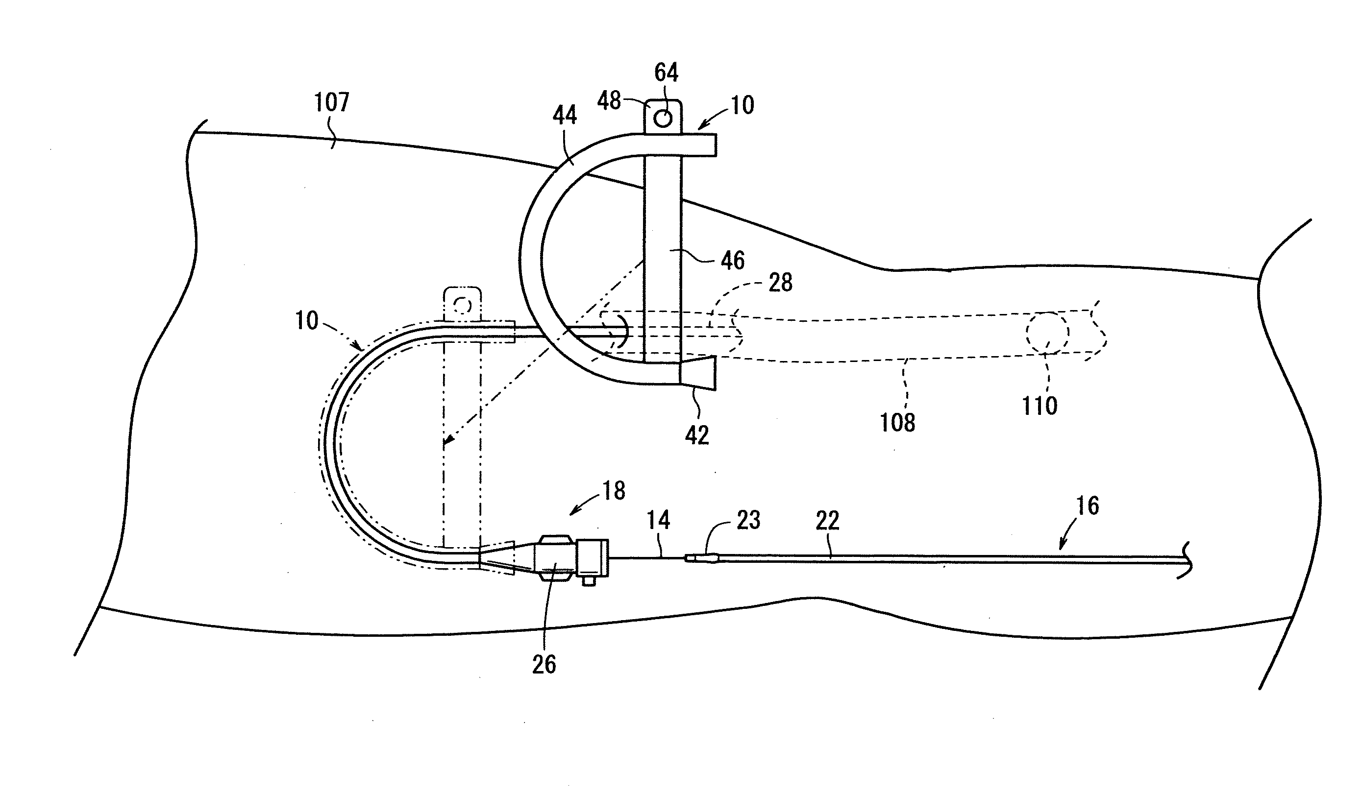
Figure 1 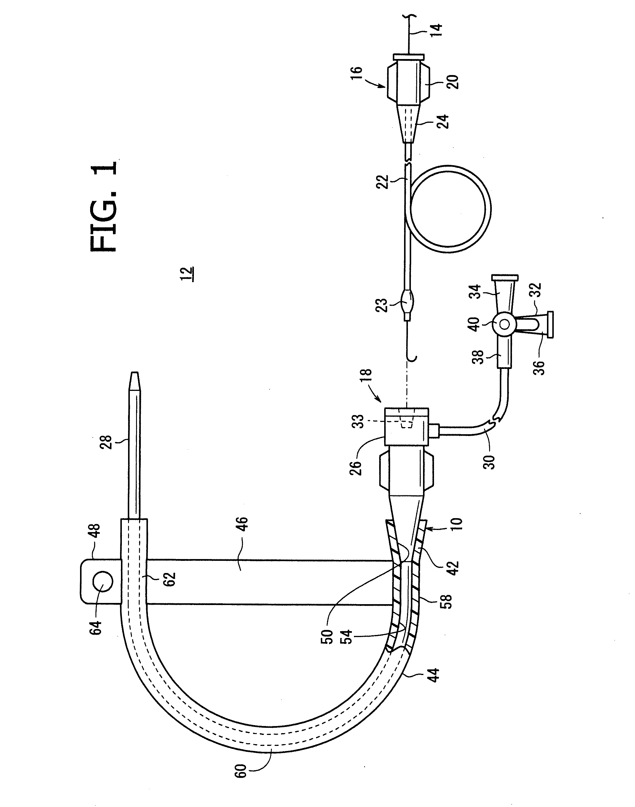
Figure 2 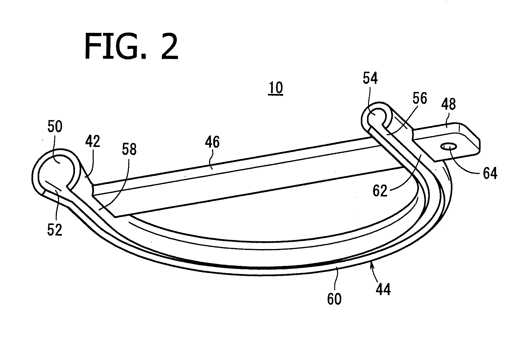
Figure 3
Abstract
Description
CROSS-REFERENCE TO RELATED APPLICATIONS
[0001] This application claims priority of Japanese Patent Application JP 2012-27185 filed on Feb. 10, 2012, Japanese Patent Application JP 2012-27182 filed on Feb. 10, 2012, and Japanese Patent Application JP 2012-208506 filed on Sep. 21, 2012, which are hereby incorporated herein by reference in their entirety.FIELD OF THE INVENTION
[0002] The present invention relates to a direction changing device to be mounted to a catheter or a sheath introducer through which the catheter is passed, a medical assembly having the direction changing device, and method of using such a medical assembly.BACKGROUND OF THE INVENTION
[0003] Conventionally, it has been a common practice to insert a catheter into a organ of a living body such as a blood vessel to deliver the catheter's distal portion to a lesion (for example, a stenosed part), and perform diagnosis or treatment on the lesion.
[0004] Specifically, as a method of percutaneously inserting a catheter into a b...
Examples
first embodiment
[0084]As shown in FIG. 1, a medical assembly 12 has a guidewire 14, a catheter 16, a sheath introducer 18, and a direction changing device 10. Incidentally, the sheath introducer 18 includes not only a sheath but also a long sheath and a guiding sheath.
[0085]The guidewire 14 is a member which is inserted in a lumen of the catheter 16 and by which the catheter 16 is guided in an organ of a living body such as a blood vessel to a predetermined target site therein. A distal portion of the guidewire 14 has been set, for example, into a roughly J-shaped form. Examples of the material forming the guidewire 14 include a polyurethane resin and stainless steel. The shape of the distal portion of the guidewire 14 is not limited to the above-mentioned shape but may be others such as a straight shape, an angular shape or the like.
[0086]The catheter 16 is configured to be percutaneously inserted into an organ of a living body, such as a blood vessel, for diagnosis or treatment of a part thereof ...
second embodiment
[0148]Now, a medical assembly 12A according to a second embodiment of the present invention will be described below, referring to FIGS. 16 to 26C. In the medical assembly 12A according to this embodiment, the same components as those of the above-described medical apparatus assembly 12 are denoted by the same reference symbols as used above, and detailed descriptions of them will be omitted.
[0149]As shown in FIG. 16, a sheath hub 26 of a sheath introducer 18 of the medical assembly 12A is a hollow member formed from a resin or the like. The sheath hub 26 includes a hub rear end section 25 having a hollow cylindrical shape, a hub intermediate section 27 which is a hollow cylindrical body smaller than the hub rear end section 25 in its outside diameter, a pair of projection pieces 29 projecting from an outer circumferential surface of the hub intermediate section 27, and a hub distal end section 31 which is provided at the distal end of the hub intermediate section 27 and tapers down ...
first modification
of Second Embodiment
[0186]A direction changing device 200a according to a first modification of this embodiment will be described below, referring to FIGS. 24A and 24B. In the direction changing device 200a according to this modification, the same components as those of the above-described direction changing device 200 are denoted by the same reference symbols as used above, and detailed descriptions of them will be omitted. The same applies also to a direction changing device 200c according to a third modification which will be described later.
[0187]As shown in FIGS. 24A and 24B, the direction changing device 200a according to this modification differs from the above-described direction changing device 200 in the configuration of an interconnecting section 220. Specifically, the interconnecting section 220 has a configuration in which one end portion of a direction changing section 202 is not integrally formed therewith; instead, there is formed a joint section 222 to which the one...