
Optical assembly and method for producing the same
a technology of optical assembly and optical elements, applied in the field of optical assembly, can solve the problem that the method takes a long time to determine the optimal position, and achieve the effect of convenient pre-operation
Patent Information
- Authority / Receiving Office
- US · United States
- Patent Type
- Applications(United States)
- Current Assignee / Owner
- Publication Date
- 2014-08-07
Smart Images
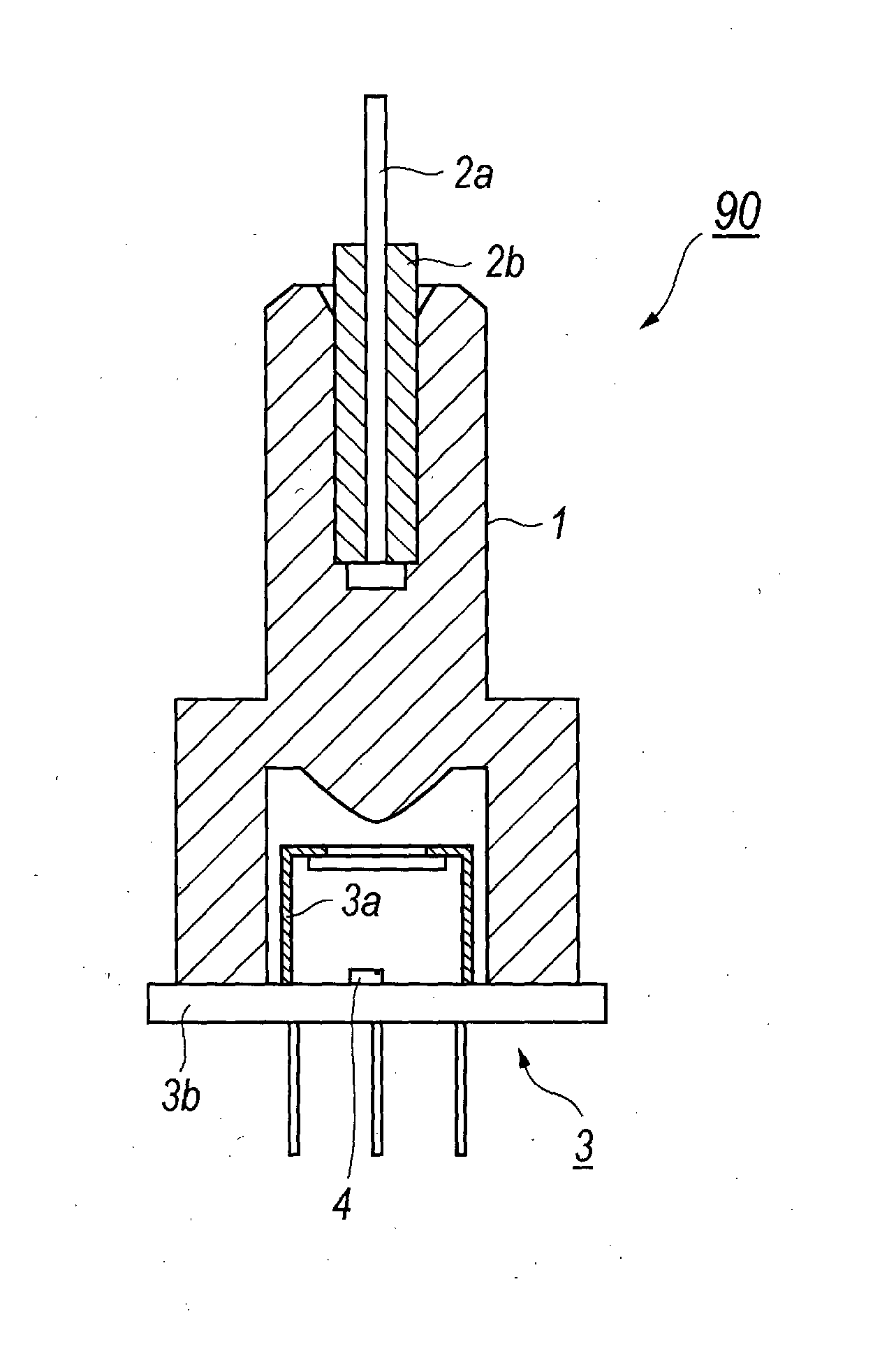
Figure 1 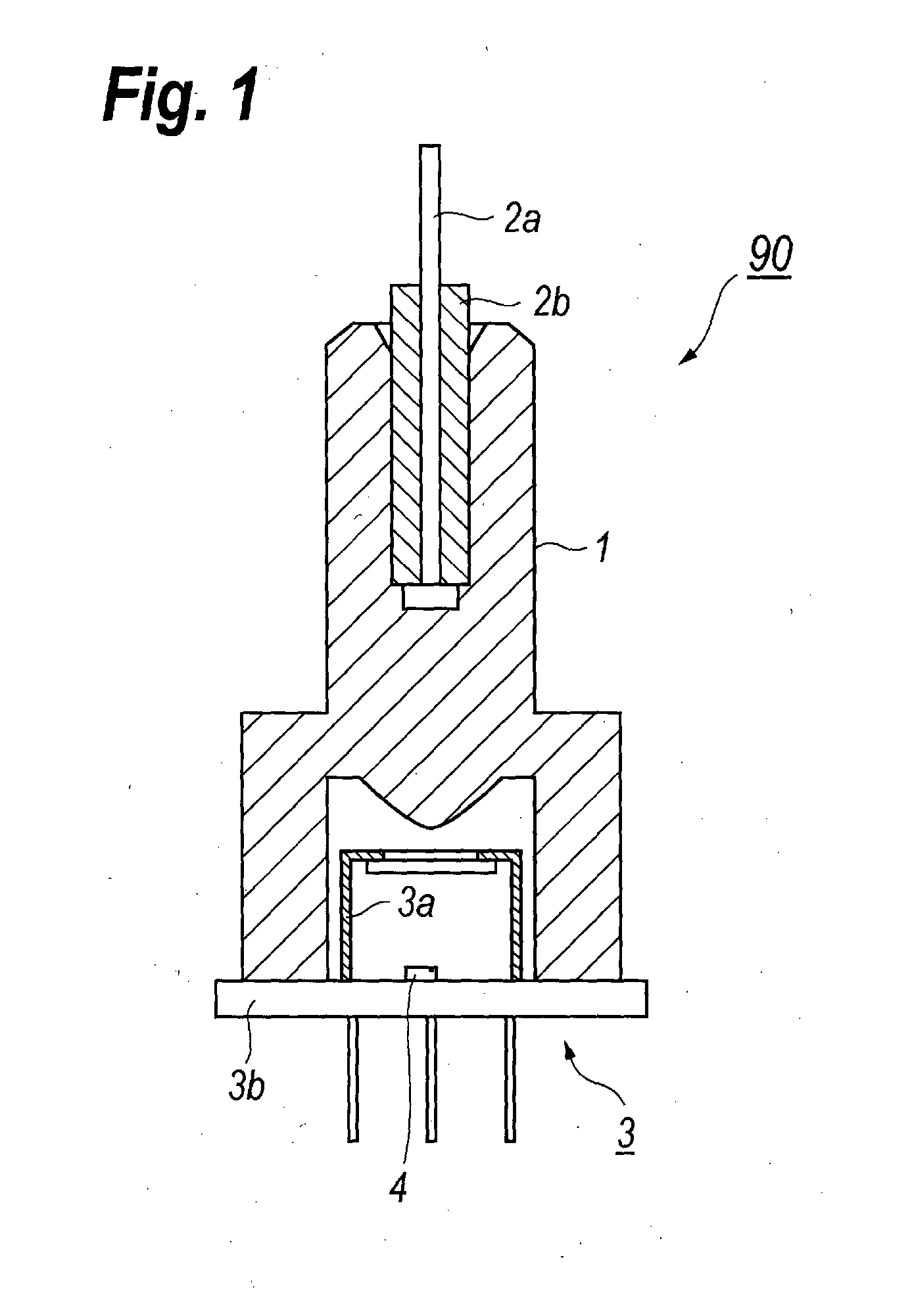
Figure 2 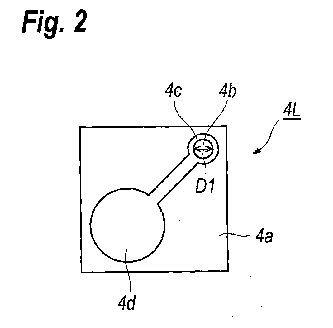
Figure 3
Abstract
Description
TECHNICAL FIELD
[0001] An embodiment of the present invention relates to an optical assembly, in particular, relates to an optical assembly including an optical device and a holder integrating a receptacle, a skirt and a lens. An embodiment of the invention further relates to a method to produce the optical assembly.BACKGROUND ART
[0002] A recent communicating system has continuously requested the higher speed and the greater capacity. An optical assembly that includes a semiconductor optical device, such as a laser diode (LD) for emitting light or a photodiode (PD) for receiving light, and a mechanism to couple the semiconductor optical device with an external optical fiber is widely applied in the optical communication system. The optical device often has, what is called, a CAN package, while, the coupling mechanism includes a sleeve to receive the external optical fiber, a skirt to receive the CAN package and a lens integrally formed with the sleeve and the skirt.
[0003] A Japanese Pa...
Examples
Embodiment Construction
[0029]Next, some preferred embodiments according to the present invention will be described as referring to drawings. In the description of the drawings, the same numerals or symbols will refer to the same or like elements without overlapping explanations.
[0030]FIG. 1 shows a cross section of an optical assembly 90 implementing with a holder 1. The optical assembly 90 includes an optical device 3 that installs a semiconductor optical device 4 therein. The optical device 3 includes a cap 3a and a base 3b for mounting the semiconductor optical device 4 thereon. The holder 1 receives in an end thereof an external optical fiber 2a with a ferrule 2b for securing a tip end of the optical fiber. The holder 1 may couple the semiconductor device 4 optically with the external optical fiber 2a. The external optical fiber 2a may be, what is called, a multi-mode fiber.
[0031]The semiconductor optical device 4 may be, for instance, a laser diode (LD), or a photodiode (PD). The embodiment shown in ...