
Method of manufacturing a composite insert
Patent Information
- Authority / Receiving Office
- US · United States
- Current Assignee / Owner
- Publication Date
- 2015-03-26
Smart Images
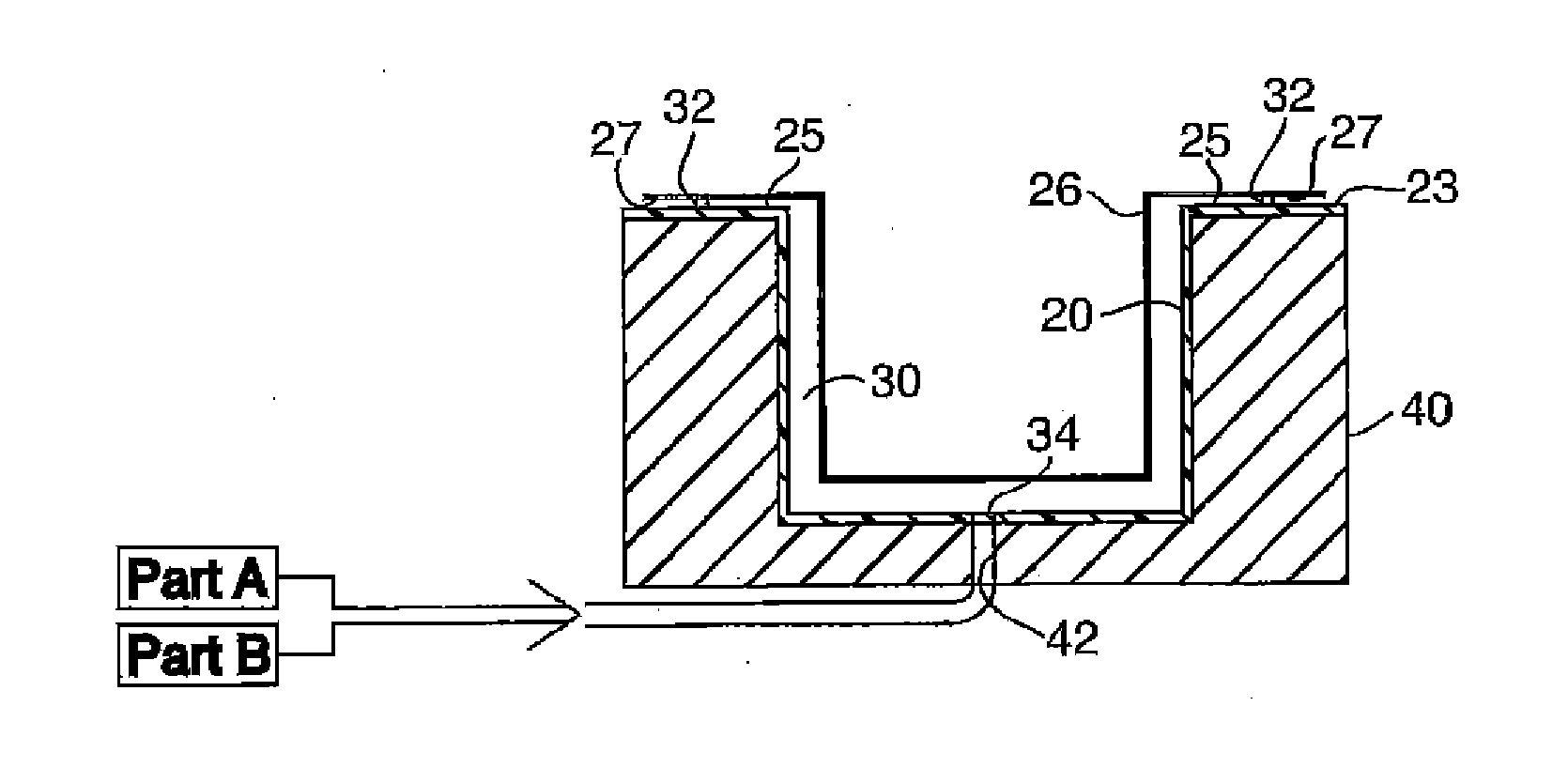
Figure 1 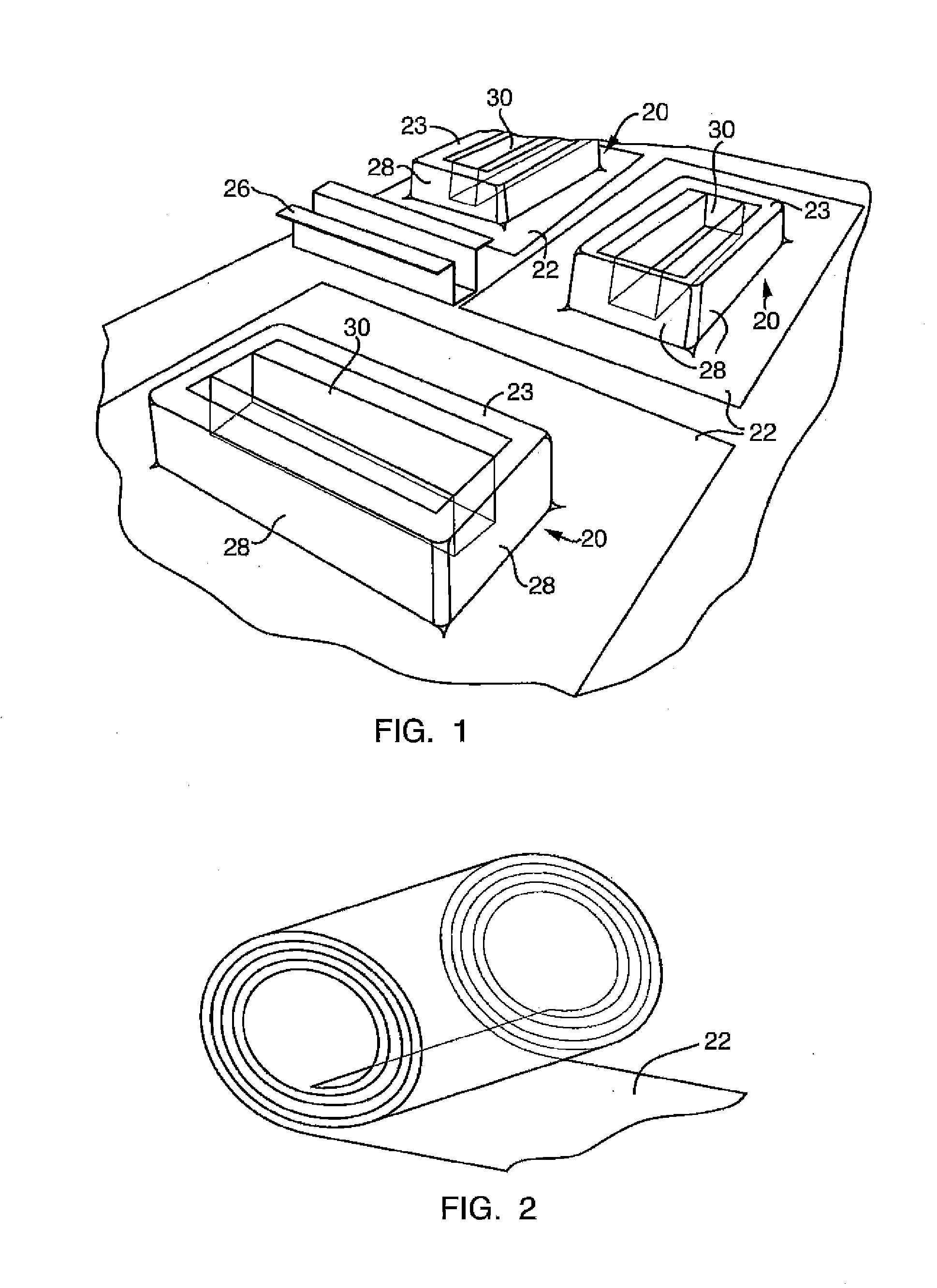
Figure 2 
Figure 3
Abstract
Description
BACKGROUND OF THE INVENTION
[0001] 1. Field of the Invention
[0002] A method of manufacturing a composite insert, useful as a structural and / or acoustic insert in a vehicle, as well as a method of manufacturing a composite part including the composite insert and a carrier, and inserts, parts and pre-packaged inserts and parts, made by these processes.
[0003] 2. Description of the Prior Art
[0004] Traditional structural and acoustic inserts are manufactured from solid reactive compositions under high temperature and high pressure via injection molding or extrusion conditions. These prior art conditions require significant time and process control monitoring during manufacturing to maintain optimum equipment operating conditions and product quality. For example, since high temperature conditions are used, the temperatures of the equipment and the composition must be closely monitored to keep the reactive composition below its cure temperature. Due to the high heat input needed to make prior a...
Examples
Embodiment Construction
[0023]Referring to the Figures, wherein like numerals indicate corresponding parts throughout the several views, a method of manufacturing a composite insert, as well as a method of manufacturing a composite part including the composite insert and a carrier joined together, first includes a step of obtaining, forming or having formed (hereinafter referred to collectively as “forming”) a polymer mold 20 for use in manufacturing the composite insert. One example of a polymer mold 20 that may result from such a forming step is generally shown in FIG. 1. The polymer mold 20 of the embodiment shown in FIG. 1 comprises a cavity 30 for accepting a composite insert composition dispensed as a flowable or low pressure injectable material. Cavity 30 terminates at flange surfaces 23, which surround the cavity and extend outward therefrom. In this embodiment, the polymer mold 20 has external walls 28 and is self supporting.
[0024]The polymer mold 20 shown in FIG. 1 is only a generic embodiment of...