
Compressor for a Vehicle Air Supply System
a compressor and air supply system technology, applied in the direction of machines/engines, liquid fuel engines, positive displacement liquid engines, etc., can solve the problem of significant increase in heat transfer
Patent Information
- Authority / Receiving Office
- US · United States
- Patent Type
- Applications(United States)
- Current Assignee / Owner
- Publication Date
- 2015-06-18
Smart Images
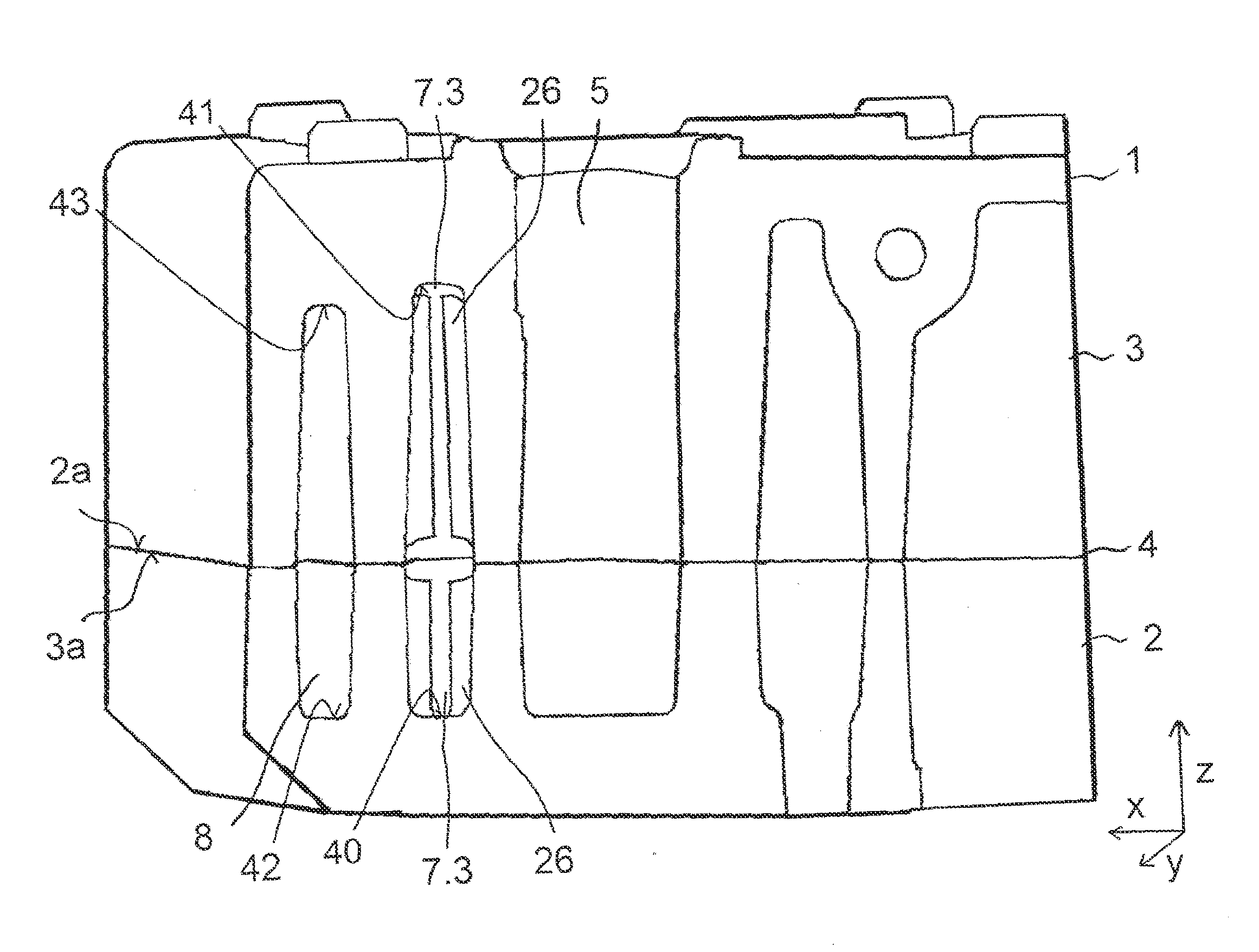
Figure 1 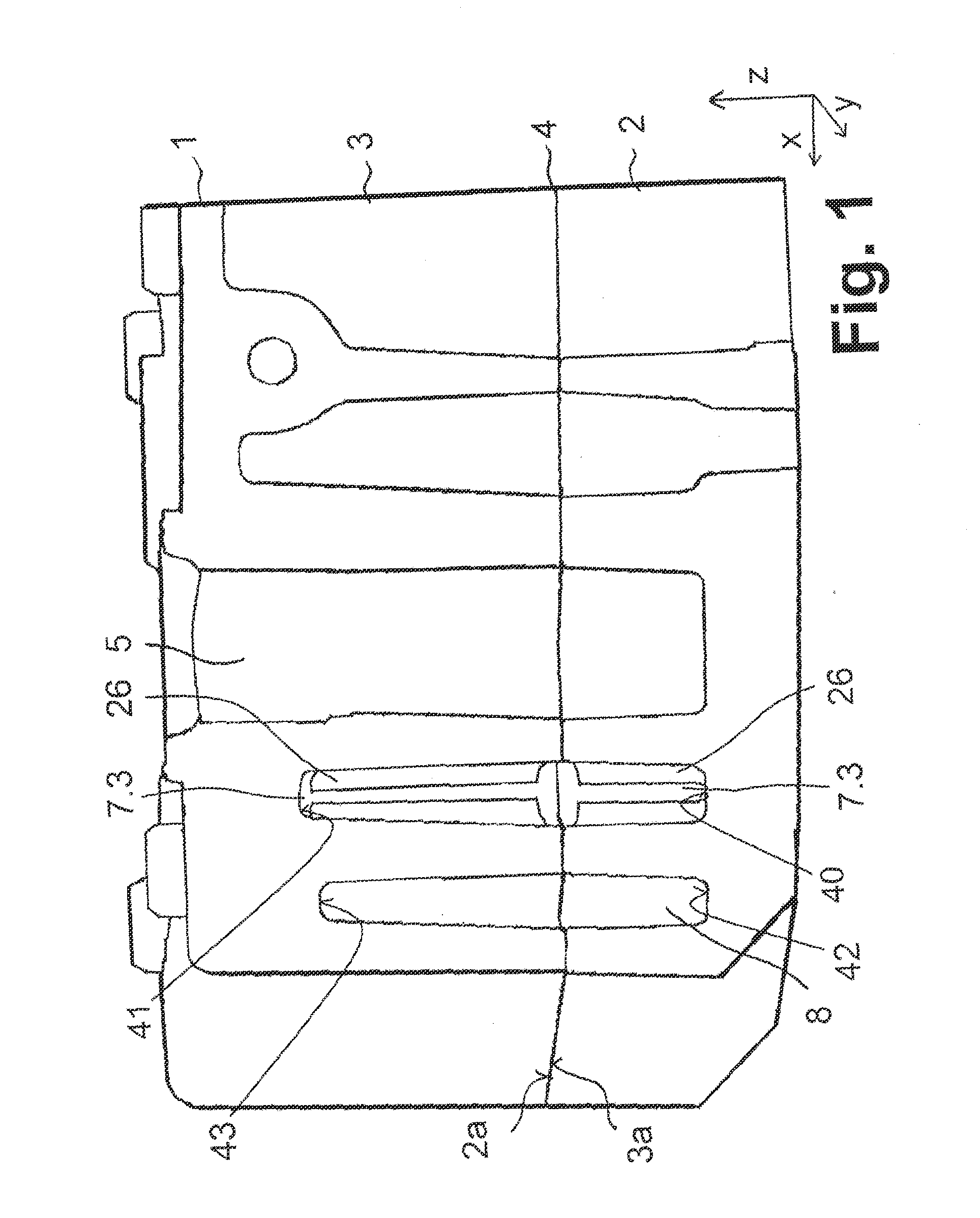
Figure 2 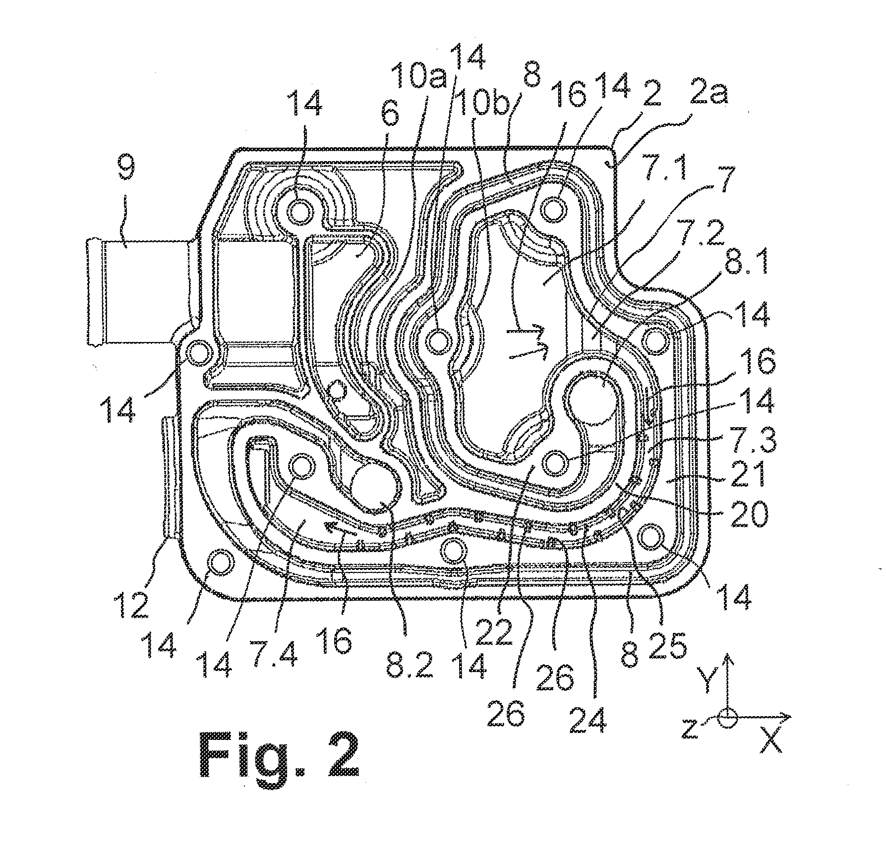
Figure 3
Abstract
Description
FIELD OF THE INVENTION
[0001] The present invention generally relates to an improved compressor for an air supply system of a vehicle, such as, for example, a utility vehicle.BACKGROUND OF THE INVENTION
[0002] Vehicle air supply systems are provided for supplying compressed air to pneumatic systems such as pneumatic brakes, pneumatic suspension systems and pneumatic assistance devices in the vehicle. A compressor of a vehicle air supply system generally comprises a compressor block (cylinder block) with an air channel system and a cylinder piston unit. The air channel system provides an inlet air passage, a discharge air passage, at least one coolant channel, and, preferably, a cylinder bore.
[0003] Air is sucked through an inlet, for example an inlet flange and the inlet air passage, to a cylinder inlet of the cylinder piston unit in which the air is compressed. The compressed air is then delivered from a cylinder outlet through the discharge air passage to an outlet, for example an outl...
Examples
Embodiment Construction
[0026]FIG. 1 shows, in cross-section, a compressor 1 comprising a manifold 2, a cover 3, and a gasket 4 disposed between the manifold 2 and the cover 3. The manifold 2 and the cover 3 are formed from metal, e.g., by a die casting process, and form a compressor block with several passages and at least one cylinder bore 5 for accommodating a piston.
[0027]The cylinder bore 5, an inlet air passage 6, a discharge air passage 7, and at least one coolant channel 8 are formed in both the manifold 2 and the cover 3. An exemplary layout of the cylinder bore 5, the inlet air passage 6, the discharge air passage 7, and the coolant channel 8 is shown in the top view of the manifold 2 depicted in FIG. 2. The gasket 4 serves to seal the cylinder bore 5 and the passages 6, 7 with respect to each other.
[0028]Referring back to FIG. 1, the manifold 2 and the cover 3 are shown stacked together in vertical direction Z with the gasket 4 between them in order to seal the channel system described herein. T...