
Frame segment for a combustor turbine interface
Patent Information
- Authority / Receiving Office
- US · United States
- Current Assignee / Owner
- Publication Date
- 2016-06-02
Smart Images
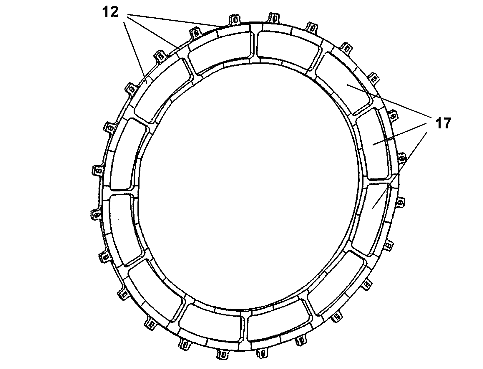
Figure 1 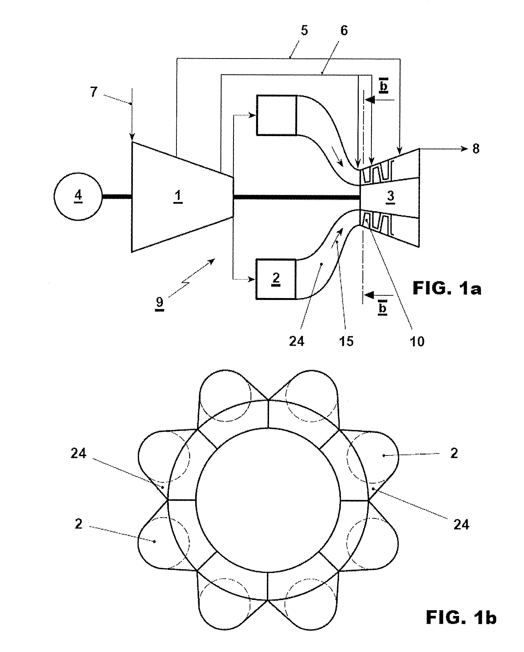
Figure 2 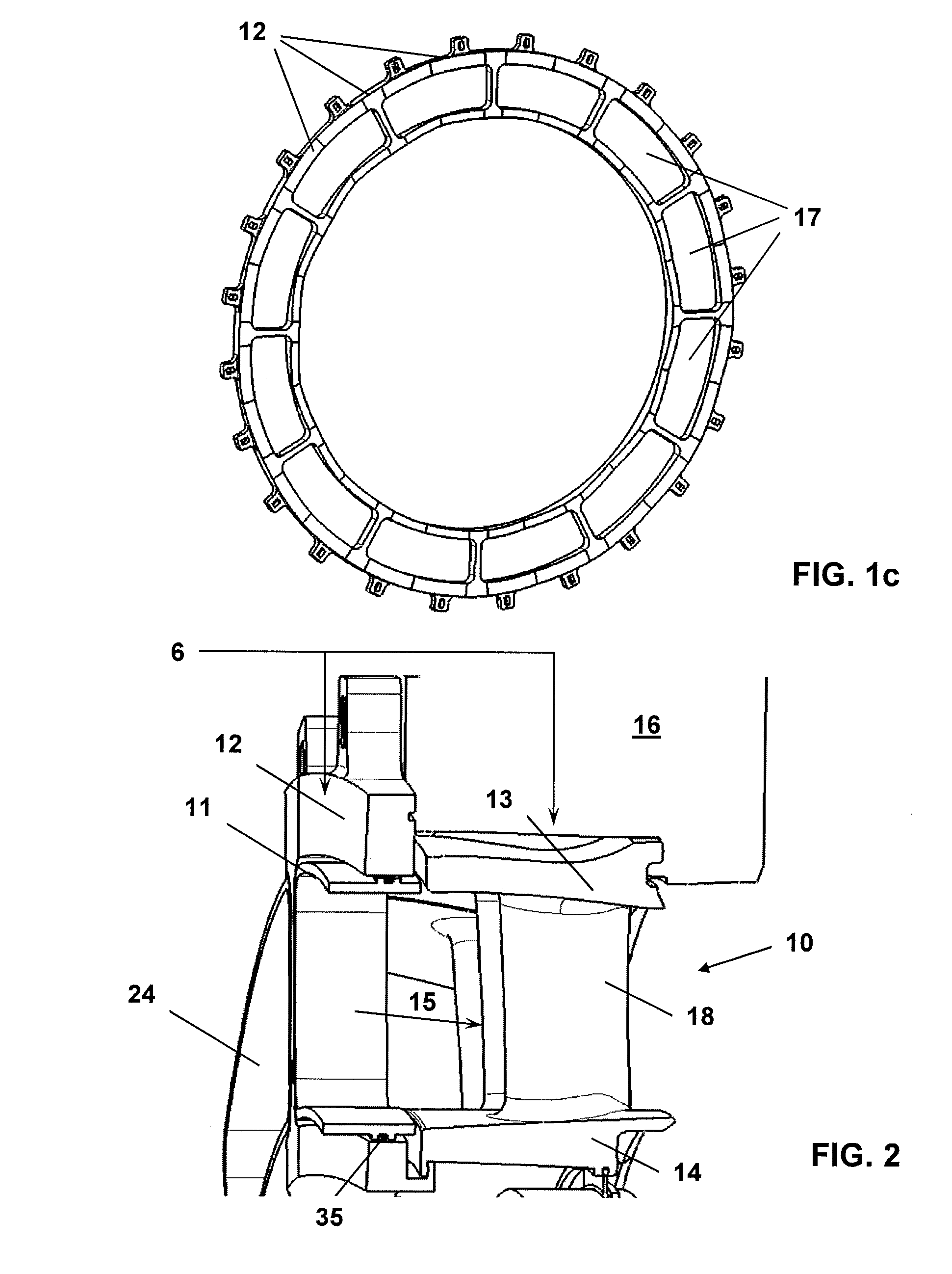
Figure 3
Abstract
Description
TECHNICAL FIELD
[0001] The invention relates to a frame segment for receiving a combustor transition piece which guides hot gases from the combustor to the turbine at the interface from a combustor to a turbine.BACKGROUND OF THE DISCLOSURE
[0002] Gas turbines with can combustors are known from various applications in power plants. Different gas turbines with can-annular combustor arrangements are known. Typically a plurality of combustors is disposed in an annular array about the axis of the turbine. Hot combustion gases flow from each combustor through a respective transition piece into the first stage vane. In addition to relative movement, e.g. due to dynamic pulsing between these components, the transition pieces and first stage vane are made of different materials and are subjected to different temperatures during operation, thereby experiencing different degrees of thermal growth. To allow such a “mismatch” at the interface of the transition pieces and the first stage vane support...
Examples
Embodiment Construction
[0036]The same or functionally identical elements are provided with the same designations below. The examples do not constitute any restriction of the invention to such arrangements.
[0037]An exemplary arrangement is shown in FIG. 1a. The gas turbine 9 is supplied with compressor inlet gas 7. In the gas turbine 9 a compressor 1 is followed by a combustion chamber comprising a plurality of can combustors 2. Hot combustion gases are fed into a turbine 3 via a plurality of combustor transition pieces 24. The can combustors 2 and combustor transition pieces 24 form a hot gas flow path 15 leading to the turbine 3. The combustor transition pieces 24 connect the can combustors 2 of the combustion chamber with the first stage vane 10 of the turbine 3.
[0038]Cooling gas 5, 6 is branched off from the compressor 1 to cool the turbine 3, the combustor 2 (not shown) and a frame segment (not shown in FIG. 1). In this example the cooling systems for high pressure cooling gas 6 and low pressure cooli...