
Determining device and determining method
Patent Information
- Authority / Receiving Office
- US · United States
- Current Assignee / Owner
- Publication Date
- 2017-11-30
Smart Images
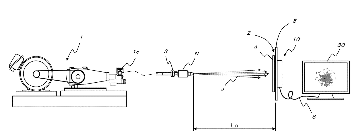
Figure 1 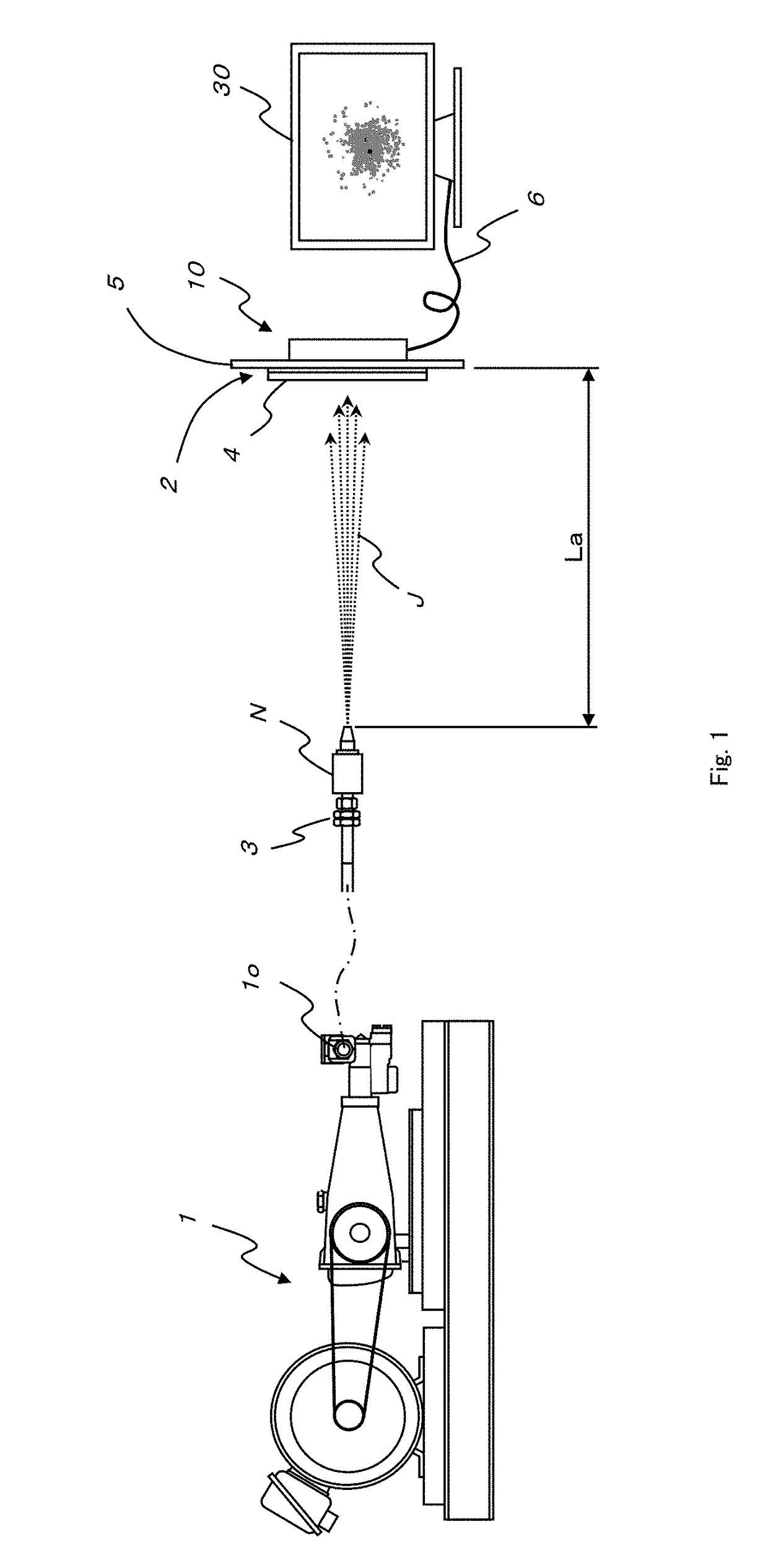
Figure 2 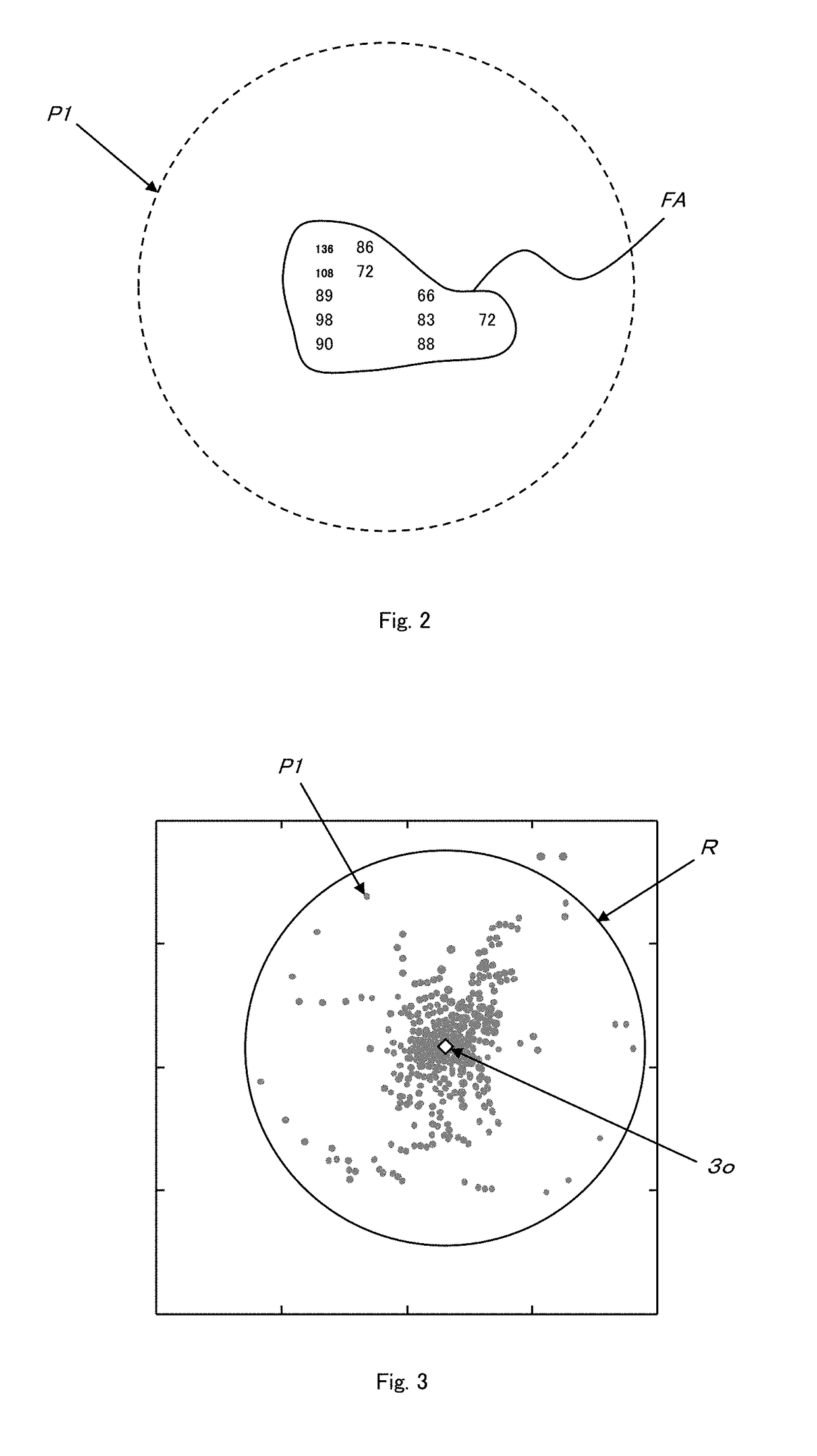
Figure 3
Abstract
Description
TECHNICAL FIELD
[0001] The present invention relates to a technology inspecting a jet nozzle which is used in a large diameter jet grouting method and constructed to generate a jet stream (a jet) with a long ground penetrating distance.BACKGROUND ART
[0002] As one of the means to improve soft ground, a large diameter jet grouting method for constructing a column-shaped improvement body having a large radial dimension in the ground is well-known.
[0003] In this large diameter jet grouting method, it is necessary to inject a jet stream with a long distance (a ground penetrating or cutting distance) to penetrate or cut into the ground which is to be subjected to construct a column-shaped improvement body having a large radial dimension. Therefore, the quality of a jet nozzle must be maintained equal or better than a certain level. When a poor-quality jet nozzle is used, a jet stream reachable distance, i.e., the ground penetrating distance is shortened.
[0004] In order to avoid a situation tha...
Examples
Embodiment Construction
[0044]An embodiment according to the present invention will now be described hereinafter with reference to the accompanying drawings.
[0045]In FIG. 1, a determining device according to the embodiment of the present invention includes a jet stream generating device (a generating pump) 1, a pressure sensing unit (a pressure sensor) 2, a controlling device (a control unit) 10, and a monitor 30 as a display device.
[0046]A nozzle N as an inspection target is disposed to an attachment 3, and the attachment 3 is fixedly provided at one end (a right end in FIG. 1) of a non-illustrated pipeline. Additionally, the other end of the non-illustrated pipeline communicates with an outlet port 10 of the generating pump 1.
[0047]A front surface (a left surface in FIG. 1) of the pressure sensor 2 is covered with a protective sheet 4 as a protective member so that it is protected from impact of a high-pressure jet stream ejected from the nozzle N.
[0048]Aback surface (a right surface in FIG. 1) of the pr...